
Method of manufacturing a perforated laminate

a manufacturing method and perforated technology, applied in the direction of saw chains, buttons, mechanical vibration separation, etc., can solve the problems of unfavorable straight perforation, tapered perforation which is not as beneficial as straight perforation, and the high number of man hours required to fabricate pin mats, etc., to achieve low cost perforation, easy to implement, and simple to understand

Inactive Publication Date: 2001-02-20
AZTEX
View PDF20 Cites 96 Cited by
  • Summary
  • Abstract
  • Description
  • Claims
  • Application Information

AI Technical Summary

Benefits of technology

It is a further object of this invention to provide such a method which dramatically reduces the number of man hours required to manufacture a perforate laminate.
It is a further object of this invention to provide such a method which results in a higher quality perforated laminate.
It is a further object of this invention to provide such a method which results in lower cost perforated laminate sheets useful in a variety of applications.
It is a further object of this invention to provide such a method which is easy to implement and simple to understand.
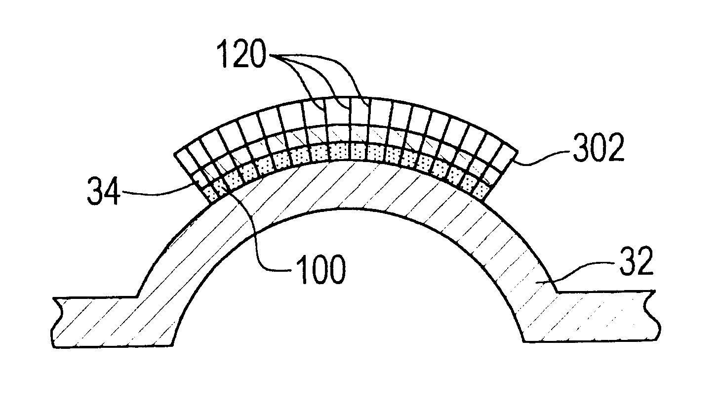
This invention results from the realization that a higher quality and lower cost perforated laminate useful for Helmholtz resonator and other structures can be manufactured, not by using a pin mat and driving the laminate onto the pin mat, but instead by keeping the laminate stationary and then driving a number of discrete pins through the stationary laminate using discrete pins supported as they are driven into the laminate by, for example, a pliable body which is much easier to manipulate and conform to the contours of the resulting laminate than the prior art pin mats which are difficult to manufacture in the first place and also difficult to work with. By using the discrete pins instead of the pin mats, straight shaft pins can be used resulting in better formed perforations. In addition, the pins are easier to remove from the perforated laminate as compared to the broken off truncated, conical shaped pins of the prior art pin mat based manufacturing methods. Since the pin mat itself is eliminated in this invention, the problems and high number of man-hours associated with fabricating and forming the pin mats and orienting them on the forming tool are eliminated.

Problems solved by technology

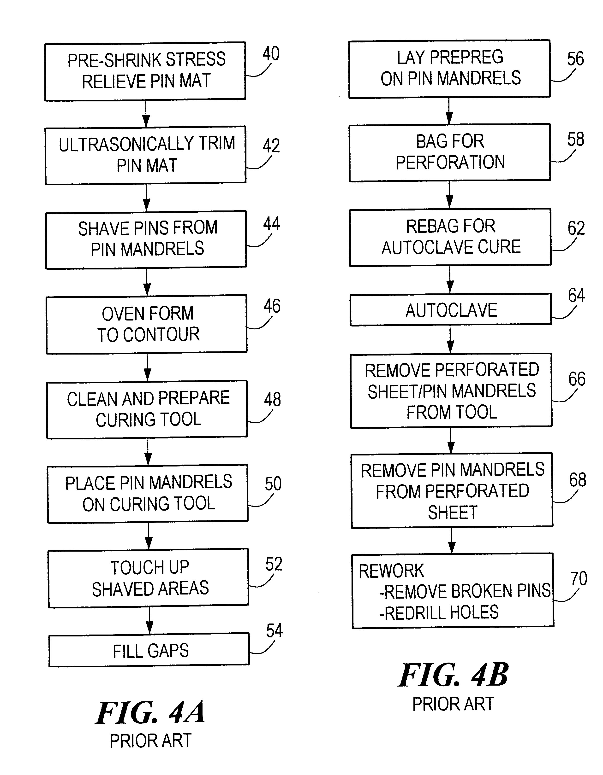
The primary limitation with this manufacturing method is the extremely high number of man hours required to fabricate the pin mats, assemble them on a forming tool, form the perforated composite laminate sheet, and to then re-work the perforations due to the fact that a number of pins usually break off from the pin mat during processing.
Another limitation is that since the pins of the pin mat must be extracted from the perforated laminate in the same direction they were inserted, the pins must have a conical shape resulting in tapered perforations which are not as beneficial as straight perforations.
Moreover, extruded pin mats, typically only available in 27".times.43" sheets, require heat treating and theremoforming before use.

Method used


Image

  • Method of manufacturing a perforated laminate
  • Method of manufacturing a perforated laminate
  • Method of manufacturing a perforated laminate

Examples


Embodiment Construction

Other objects, features and advantages will occur to those skilled in the art from the following description of a preferred embodiment and the accompanying drawings, in which:

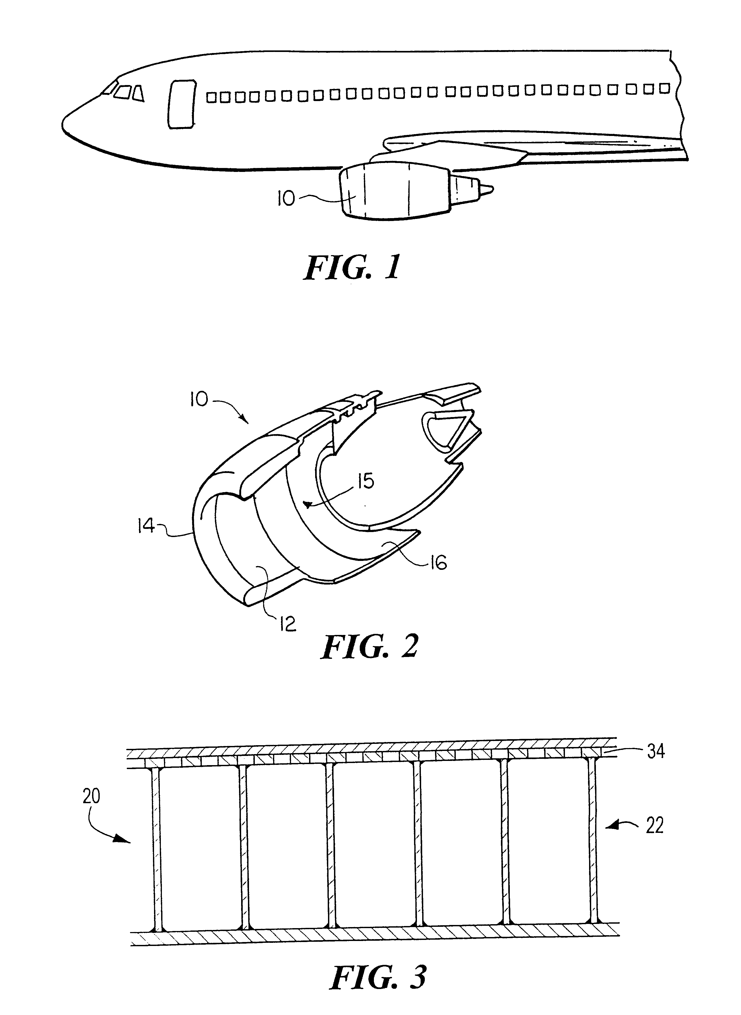
FIG. 1 is a partial view of an aircraft having a nacelle that utilizes sound attenuation structures having perforated laminates manufactured in accordance with the subject invention;

FIG. 2 is a partial cutaway perspective view of a portion of the nacelle shown in FIG. 1 and illustrates the typical arcuate acoustic structures which utilize a perforated laminate manufactured in accordance with the subject invention;

FIG. 3 is a sectional side view of a Helmholtz resonator sound attenuation structure incorporating a perforated laminate sheet in accordance with the subject invention;

FIGS. 4A and 4B are flow charts depicting the primary manufacturing steps of the prior art methods of making a perforated laminate using pin mats;

FIG. 5 is a schematic view of a prior art pin mat;

FIG. 6 is a schematic end view of the pin...


PUM


Abstract

A method of making a perforated laminate wherein a pliable perforation device having plurality of holes and plurality of perforation pins in the holes is assembled on a laminate; the pins are driven through the uncured laminate to perforate the laminate; the laminate is then staged or cured with pins in place; and the pins are then removed from the cured laminate and pushed back into the perforation device for reuse thereof.

Description

This invention relates to a method of manufacturing a perforated laminate useful, for example, as a part of a Helmholtz resonator structure.BACKGROUND OF INVENTIONPerforated laminate sheets are used in a variety of application including Helmholtz resonators which include a honeycomb core supporting a perforated laminate face sheet. Such structures are used to form the arcuate inner surfaces of the nose cowl and thrust reverser components of a nacelle system of a commercial jet aircraft.Surprisingly, perforating a composite laminate is not a straight forward process. The problems with drilling, abrasion, stamping, water jet, laser beam, and other similar processes are documented in U.S. Pat. Nos. 5,268,055 and 5,252,279 incorporated herein by this reference.So, these and other patents (e.g., U.S. Pat. Nos. 4,541,879; 4,390,584; 5,419,865; 4,612,737; and 4,486,372) delineate a different perforation methodology wherein a pin mat is used to perforate the composite laminate. The pin mat ...

Claims


Application Information

Patent Timeline
IPC IPC(8): B29C70/04B26F1/24B29C70/54B26F1/00B26D7/08B64F5/00
CPCB26D7/086B26F1/24B29C70/545B64F5/0009Y10S425/037B64F5/10Y10T83/9314Y10T83/9466
Inventor BLANEY, ERICFUSCO, THOMAS M.FREITAS, GLENN A.RICH, DAVID
Owner AZTEX
Learn More