
Ellipsoidal projection mapping

a projection mapping and ellipsoidal technology, applied in the field of computer graphics, can solve the problems of poor texture mapping, poor texture mapping, and high degree of distortion of conventional projection projection bodies, and achieve the effect of improving the accuracy of projection projection

Inactive Publication Date: 2001-02-20
AUTODESK INC
View PDF4 Cites 17 Cited by
  • Summary
  • Abstract
  • Description
  • Claims
  • Application Information

AI Technical Summary

Benefits of technology

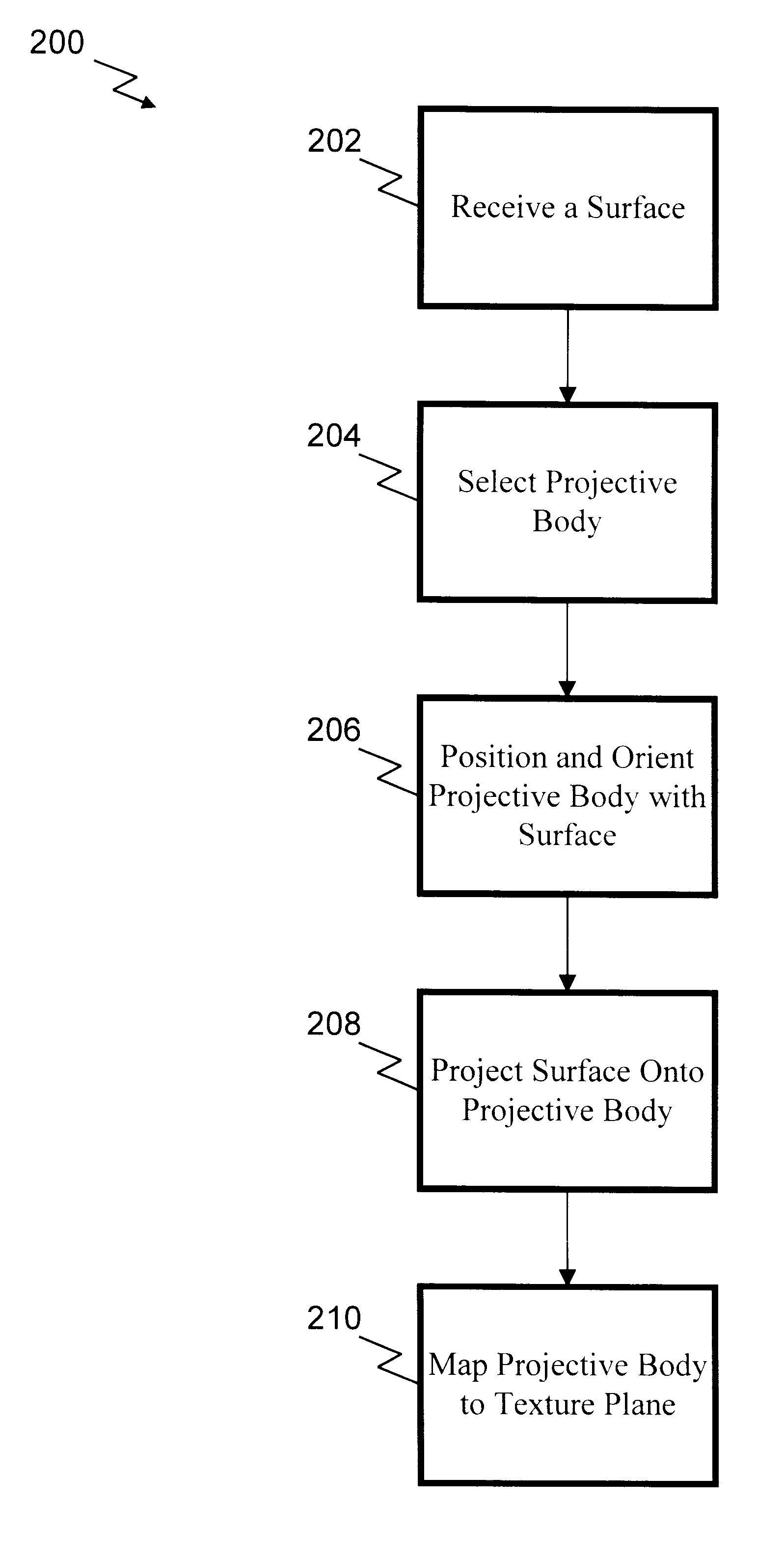
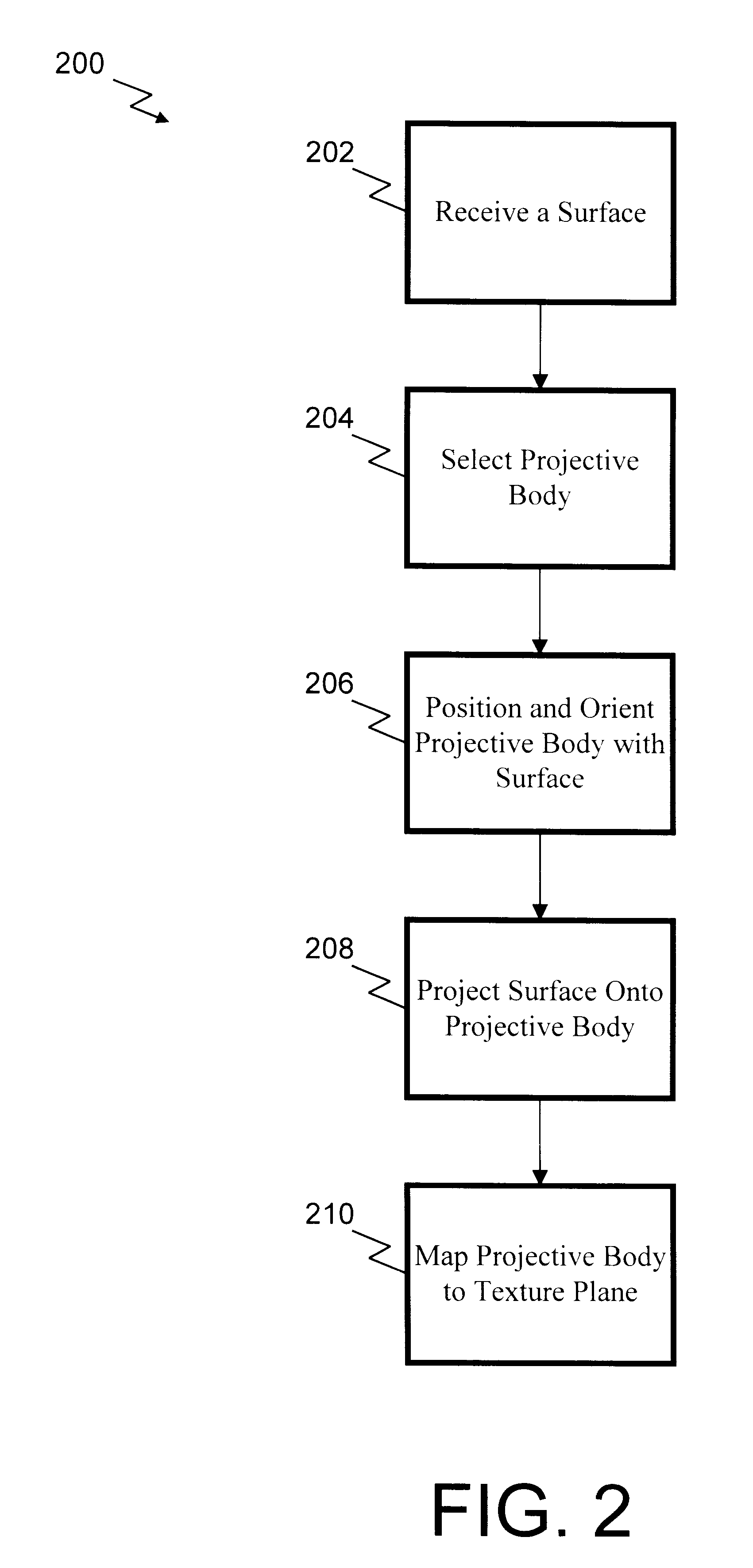
Returning to FIG. 2, in step 208, surface 300 (positioned and oriented) is projected onto projective body 302. In a preferred embodiment, an ellipsoidal projective body is used and the projection of step 208 is preferably accomplished by calculating ellipsoidal coordinates (u', v', w') for each point (x, y, z) on surface 300, and then discarding the w' coordinate. Discarding the w' coordinate has the effect of projecting surface 300 onto the surface of ellipsoidal projective body 302. All those points on surface 300 which have ellipsoidal coordinates sharing the same u' and v' coordinates but varying w' coordinates, map to the same point on ellipsoidal projective body 302, i.e., these points lie on common lines of projection. Therefore, the mapping between surface 300 and ellipsoidal projective body 302 is not necessarily one-to-one. For example, surfaces 300 containing certain concavities can result in a non-one-to-one projection to projective body 302. Though non-optimal, this trait is shared by all projection methods for texture mapping.

Problems solved by technology

Manually positioning and orienting a projective body can be time consuming and, if not done correctly, can result in mappings that either make poor use of the texture rectangle or introduce a high degree of distortion.
Furthermore, conventional projective bodies used for projection texture mapping often don't "fit" surfaces very well, because they have limited degrees of freedom within which they can be altered.
Requiring a user to select an appropriate projective body can also lead to mistakes and poor texture mappings.

Method used


Image

  • Ellipsoidal projection mapping
  • Ellipsoidal projection mapping
  • Ellipsoidal projection mapping

Examples


Embodiment Construction

Overview of the Environment

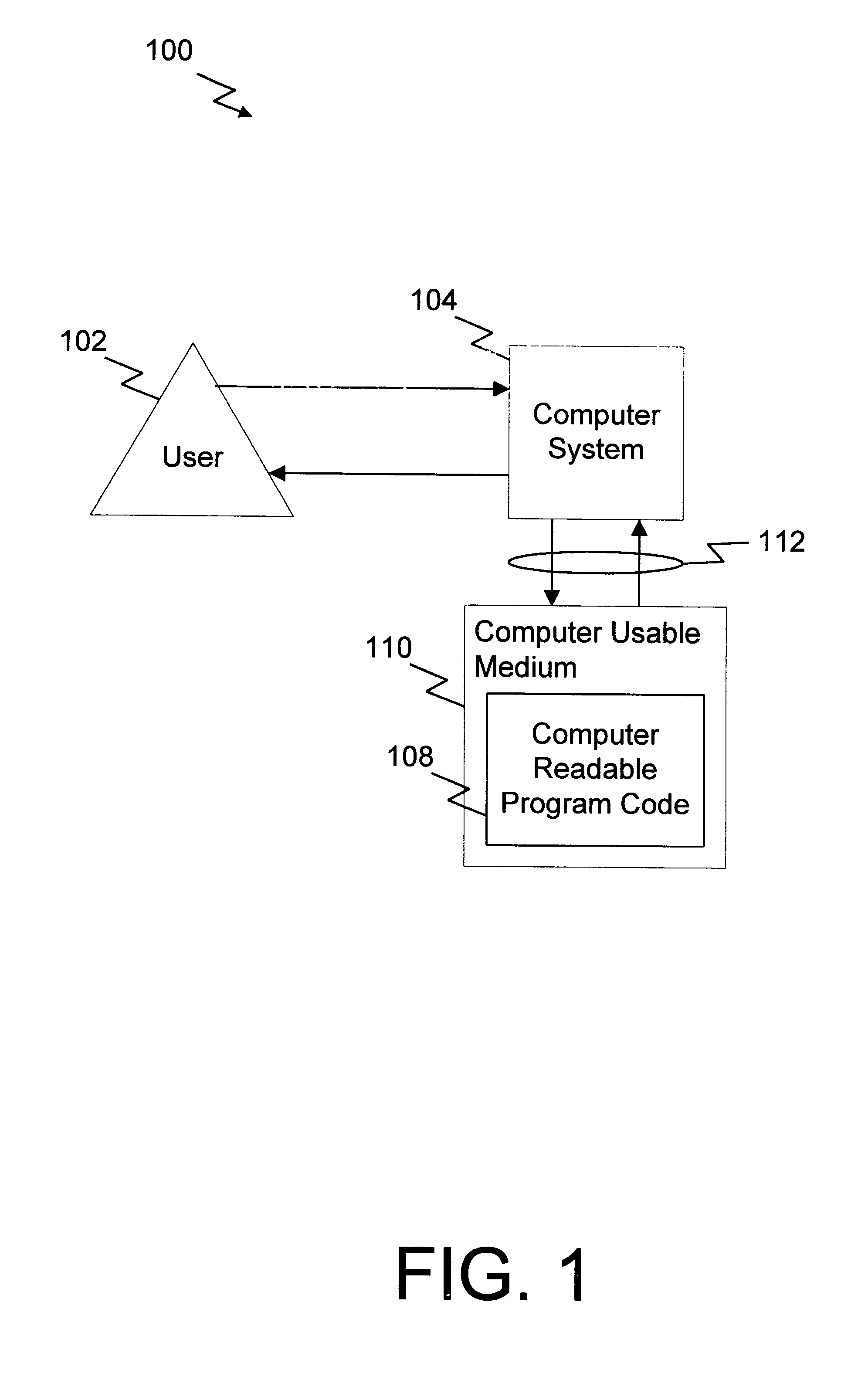
FIG. 1 is a block diagram of a digital computer environment 100 within which the present invention is used. A user 102 interacts with a computer system 104 according to conventional user interface techniques. The present invention is preferably implemented as computer readable program code 108 stored on a computer usable medium 110, accessed via a communication link 112. Computer system 104 operates under the control of computer readable program code 108.

Computer system 104 represents any computer system known to those skilled in the art with sufficient capability (i.e., both memory and processing power) to execute computer readable program code 108. Examples of computer system 104 include, but are not limited to, a microcomputer, workstation, or terminal connected to a central processor.

Computer usable medium 110 is any digital memory capable of storing computer readable program code 108. Examples of computer usable medium 110 include, but are not limited...


PUM


Abstract

A projective body is aligned with a surface to generate texture coordinates for the surface. The present invention includes selecting an appropriate projective body for a given surface, orienting and positioning the surface with respect to the projective body, projecting the surface onto the projective body, and then mapping the projective body onto the texture rectangle. An inertial ellipsoid is used to orient the surface and the projective body. The inertial ellipsoid can also be used as the projective body. Ellipsoidal coordinates are preferably used to project the surface onto the projective body.

Description

1. Field of the InventionThe present invention relates generally to computer graphics, and more particularly to the generation of texture coordinates for a surface using an ellipsoidal projective body.2. Related ArtIn the field of computer graphics, texture mapping is a well known technique for imparting realism to rendered surfaces. A surface S is amenable to this technique if there is a defined mapping M from S to a rectangular region T known as texture space. The region T is typically identified with an image whose values modulate or define, via the mapping M, rendered attributes of the surface S.For a parametric surfaceS(u,v)=(X(u,v), Y(u,v), Z(u,v))such a mapping exists and is simply the inverse mapping S.sup.-1. However, for non-parametric surfaces (e.g., implicit or polygonal surfaces), such a mapping does not exist a priori. Mappings must be therefore be constructed for these non-parametric surfaces.Planar, cylindrical or spherical projections are commonly used methods for c...

Claims


Application Information

Patent Timeline
IPC IPC(8): G06T15/10G06T15/20G06T15/04
CPCG06T15/04
Inventor LIEPA, PETER
Owner AUTODESK INC
Learn More