
Sensor chip, laminated wafer for sensor chip and manufacturing method of sensor chip

a technology of sensor chip and manufacturing method, which is applied in the direction of fluid pressure measurement, pressure difference measurement between multiple valves, instruments, etc., can solve the problems of noise pickup, difficult chip attachment, and complicated jigs

Inactive Publication Date: 2001-02-27
NAGANO KEIKI
View PDF2 Cites 8 Cited by
  • Summary
  • Abstract
  • Description
  • Claims
  • Application Information

AI Technical Summary

Problems solved by technology

However, since the conductive layer 205B of the signal receiving portion 205 stretches to a lower end (a periphery of the second glass substrate 202 remote from the diaphragm 200A) of the sensor chip, the circuit substrate touches the conductive layer 205B when the chip is mounted to the circuit substrate, thereby causing possible electric failure such as noise pickup.
However, the structure of the jigs can be too complicated in the above arrangement, thereby making the attachment of the chip difficult.
Additionally, since the small chip has to be carefully handled by a pair of tweezers and the like and the chips are collectively produced from a single wafer by a order of some hundreds pieces when the chip is attached to the jig, enormous time is necessary for attaching all the chips.
Accordingly, it is difficult to secure an area for the signal receiving portion to ensure the bonding strength and the electrode has to be extended to the outside.
However, following disadvantage occur in the above arrangement.
In addition, the aforesaid conventional sensor chip has a disadvantage accompanied by anodic bonding electrode as well as the above-described disadvantage of signal receiving portion.
Further, since the anodic-bonding electrode 208 visually blocks, using automation machinery is impossible for improving work efficiency.
Second, when the anodic-bonding electrode 208 is retained on the sensor chip, a part of the anodic-bonding electrode 208 can be peeled off to cause contamination problem and removing work can be troublesome for marketing as a pressure sensor.

Method used


Image

  • Sensor chip, laminated wafer for sensor chip and manufacturing method of sensor chip
  • Sensor chip, laminated wafer for sensor chip and manufacturing method of sensor chip
  • Sensor chip, laminated wafer for sensor chip and manufacturing method of sensor chip

Examples


first embodiment

[First Embodiment]

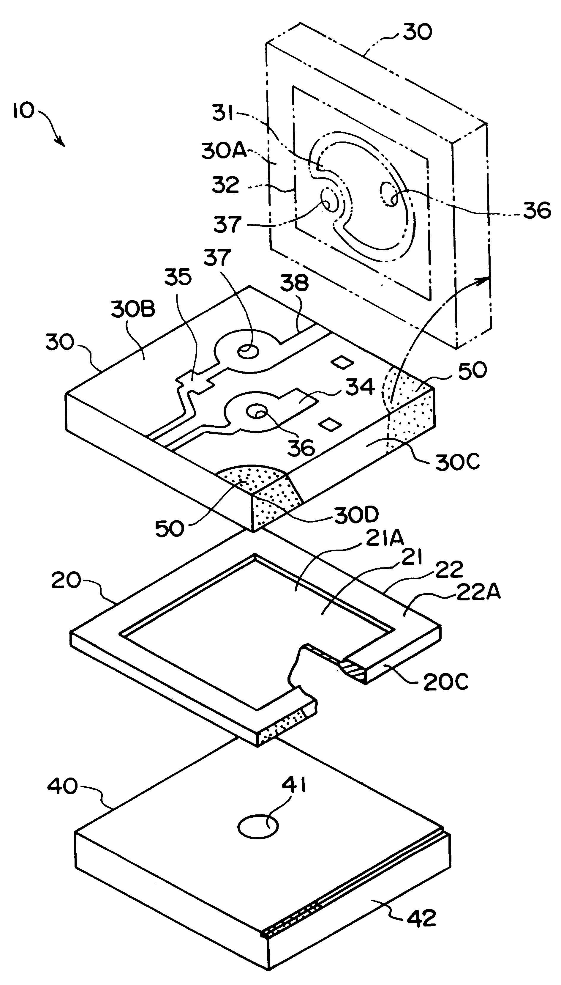
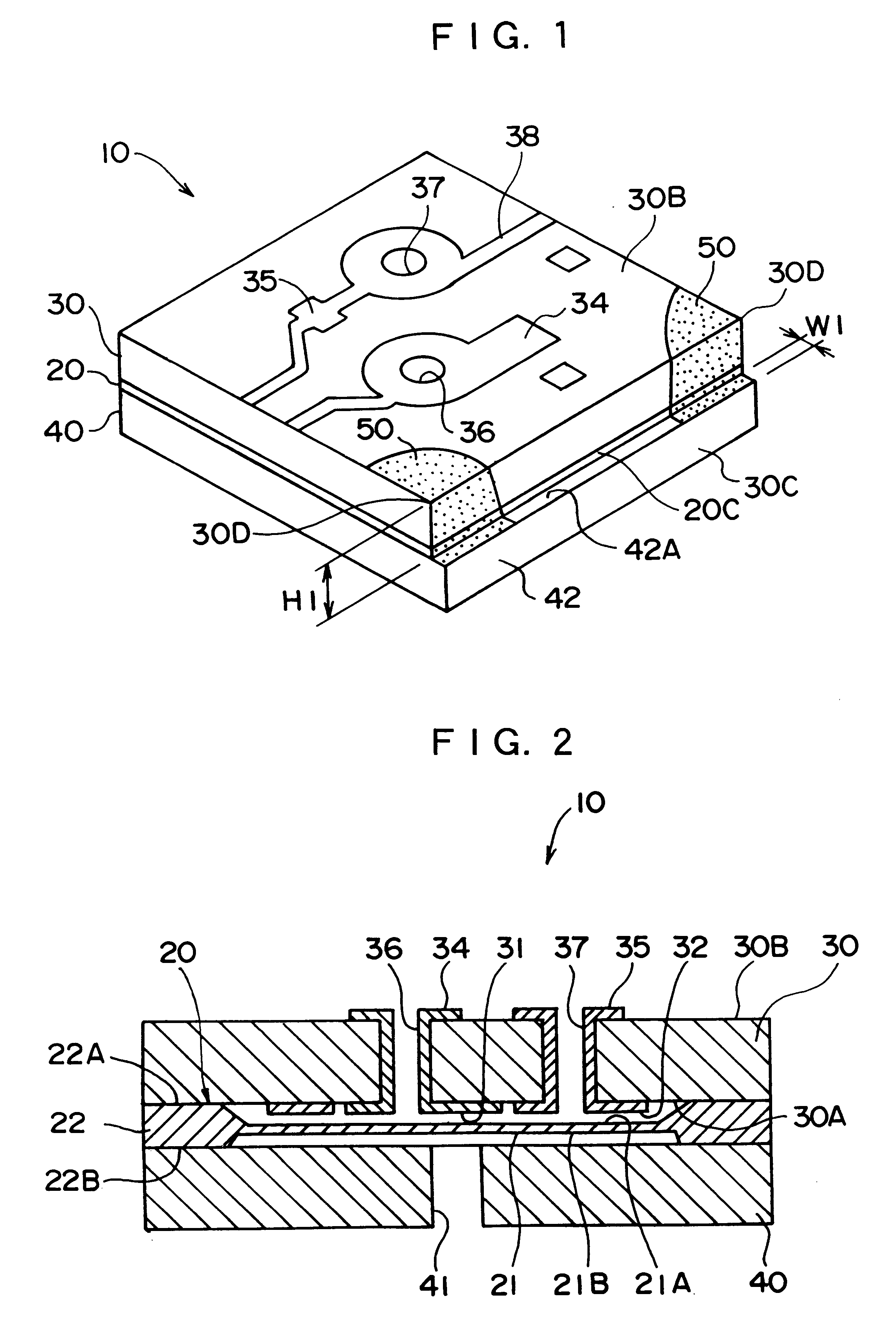
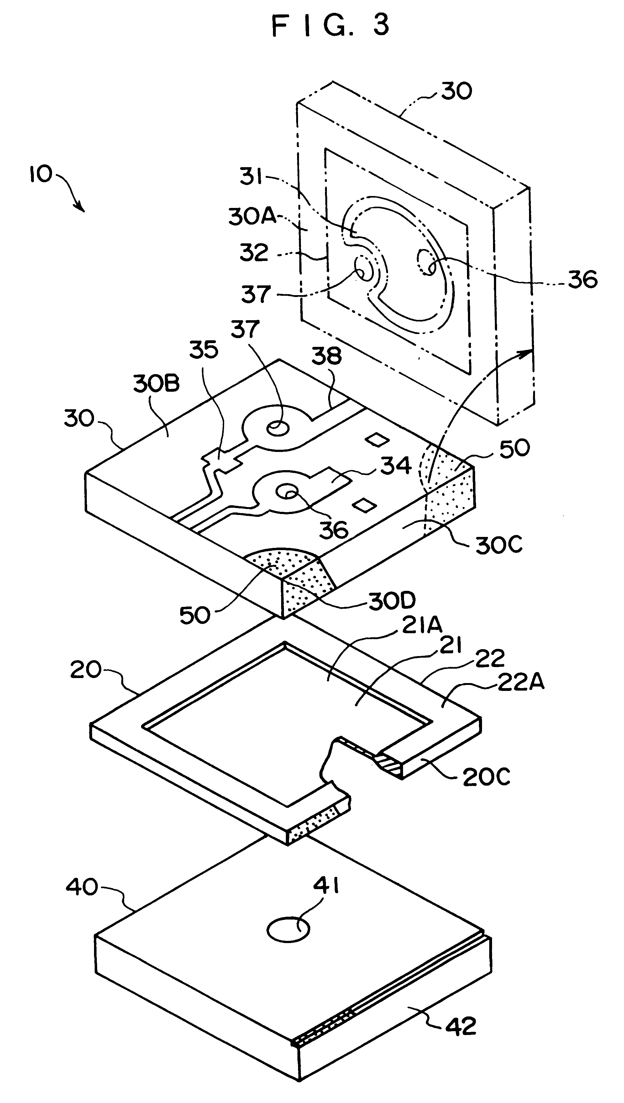
The present embodiment relates to a pressure sensor chip 10 to which the present invention is applied. The pressure sensor chip 10 is an electro-capacitance type pressure sensor chip in which the pressure is detected as a change in electrostatic capacitance, the pressure sensor chip being a laminated chip in practical use as shown in FIG. 1. The pressure sensor chip 10 is manufactured collectively in plural as a laminated wafer 60 as shown in FIG. 6, and is cut in the form shown in FIG. 1.

An arrangement of the pressure sensor chip 10, an arrangement of the laminated wafer 60 and specific steps for manufacturing the pressure sensor chip 10 from the laminated wafer 60 will be described below.

[Pressure Sensor Chip]

As shown in FIGS. 1 to 3, the pressure sensor chip 10 includes an upper glass 30 as first substrate, a lower glass 40 as second substrate and an electrode layer 20 sandwiched between them.

The electrode layer 20 is made of conductive silicon, the periphery th...

second embodiment

[Second Embodiment]

A pressure sensor 130 according to the second embodiment of the present invention is shown in FIG. 11.

The pressure sensor 130 is a differential-pressure type having first pressure sensor 131 and second pressure sensor 132, which is so-called a combined-chip.

Incidentally, identical reference number is applied to the same component as the first embodiment and description thereof is omitted.

The pressure sensor 130 according to the present embodiment has an integral lower glass 134 as a common base of the first and the second pressure sensor 131 and 132 and the extension 42 described in the first embodiment is not provided. Further, the respective signal receiving portions 50 are not formed on the comer but is formed of conductive layer provided at an approximate center of the mutually opposing periphery.

The first pressure sensor 131 and the second pressure sensor 132 are arranged partially differently in the area, configuration, thickness (or one of them) of the diap...


PUM

PropertyMeasurementUnit
thickaaaaaaaaaa
thickaaaaaaaaaa
thickaaaaaaaaaa

Abstract

In a pressure sensor chip (10), an extension (42) is provided on a lower glass (40) and a signal receiving portion (50) of a conductive layer is formed from a surface (42A) of an extension (42) to an upper surface (30B) of an upper glass (30). Accordingly, the signal receiving portion (50) does not touch a circuit substrate when the pressure sensor chip (10) is mounted to the circuit substrate and the like, thereby preventing electric failure such as noise pickup of the signal receiving portion (50). Further, since the signal receiving portion (50) is formed by the conductive layer, no particular space for receiving electric potential from a diaphragm is necessary, thereby enabling size reduction of the pressure sensor chip (10). Since an anodic-bonding electrode (83) is disposed on a border (62) and is cut and removed in separating as the pressure sensor chip (10), visual check is not obstructed and contamination by being peeled-off can be prevented.

Description

1. Field of the InventionThe present invention relates to a sensor chip (semiconductor component for sensors) used for sensors for measuring pressure, acceleration, flow rate, temperature and the like, manufacturing method of the sensor chip and a laminated wafer used for manufacturing the sensor chip.2. Description of Related ArtJapanese Patent Application Laid-Open No. Hei 8-235387 discloses a sensor chip used, for example, for electro-capacitance type pressure sensor.The chip has a laminated structure where an electrode layer 200 is sandwiched between two glass substrates 201 and 202. As shown in FIG. 15, the electrode layer 200 is composed of a conductive silicon substrate and has a thick portion 200B around thin diaphragm 200A. The first glass substrate 201 and the second glass substrate 202 is bonded to the peripheral thick portion 200B. A predetermined gap is respectively formed between the respective glasses 201, 202 and the diaphragm 200A because the diaphragm 200A is thin ...

Claims


Application Information

Patent Timeline
Patent Type & Authority Patents(United States)
IPC IPC(8): G01L9/00G01L9/12G01L13/06G01P15/125H01L29/84
CPCG01L9/0073
Inventor SEKIMORI, YUKIMITSUYOKOYAMA, SEIICHIKAISE, FUMIO
Owner NAGANO KEIKI
Learn More