Method for scanning non-overlapping patterns of laser energy with diffractive optics

a laser energy and diffractive optics technology, applied in the field of medical systems and methods, can solve problems such as uneven treatment profiles

Inactive Publication Date: 2001-02-27
AMO MFG USA INC
View PDF9 Cites 53 Cited by
  • Summary
  • Abstract
  • Description
  • Claims
  • Application Information

AI Technical Summary

Benefits of technology

By "scanning," it is mean that an ablation light beam is aimed or "scanned" to successive, discrete locations on the corneal surface, and that those locations are then exposed to a predetermined amount or dosage of the light energy. Usually, the laser system will be operated in a pulsed manner, and the exposure at any particular location will result from a number of pulses which occur over a very short time period. The total area of the cornea to be treated, referred to hereinafter as the "ablation zone," is eventually treated as the ablative light beam scanned over the zone. As discussed above, however, prior systems which employ light beams having circular cross-sections result in an uneven treatment profile since adjacent circular geometries overlap in an uneven manner. The present invention significantly improves the uniformity of treatment, in some embodiments by employing beam geometries which are selected to cover the entire ablation zone without substantial overlap between adjacent beam patterns. In this way, the entire ablation zone can be treated with each segment or portion of the zone receiving the desired dosage of ablative energy.
The present invention provides a number of specific improvements over such prior corneal ablation methods and systems. First, the present invention provides methods and systems for treating an ablation zone with ablative light beams having annular or ring-shaped geometries. The ablation zone will usually have a circular geometry with a diameter in the range from 0.1 mm to 10.0 mm, usually from 1.0 mm to 6.0 mm. By employing successive ablative light beams having concentric, annular geometries, the entire ablation zone can be treated without substantial overlap between adjacent annular beams. That is, by utilizing adjacent annular light beams where the outer diameter of one beam is substantially equal to the inner diameter of the adjacent beam, each annular segment of the ablation zone will be treated only once. The use of annular beam geometries is particularly preferred since it facilitates dosage control over the ablation zone. That is, it will be relatively easy to expose the radially outward segments and radially inward segments to different energy dosages by properly selecting the beam intensity and dosage time of each of the radially positioned annular light beams. As described below, these annular beam geometries may also treat an ablation zone using substantial overlap between successive beams.

Problems solved by technology

As discussed above, however, prior systems which employ light beams having circular cross-sections result in an uneven treatment profile since adjacent circular geometries overlap in an uneven manner.

Method used


Image

  • Method for scanning non-overlapping patterns of laser energy with diffractive optics
  • Method for scanning non-overlapping patterns of laser energy with diffractive optics
  • Method for scanning non-overlapping patterns of laser energy with diffractive optics

Examples


Embodiment Construction

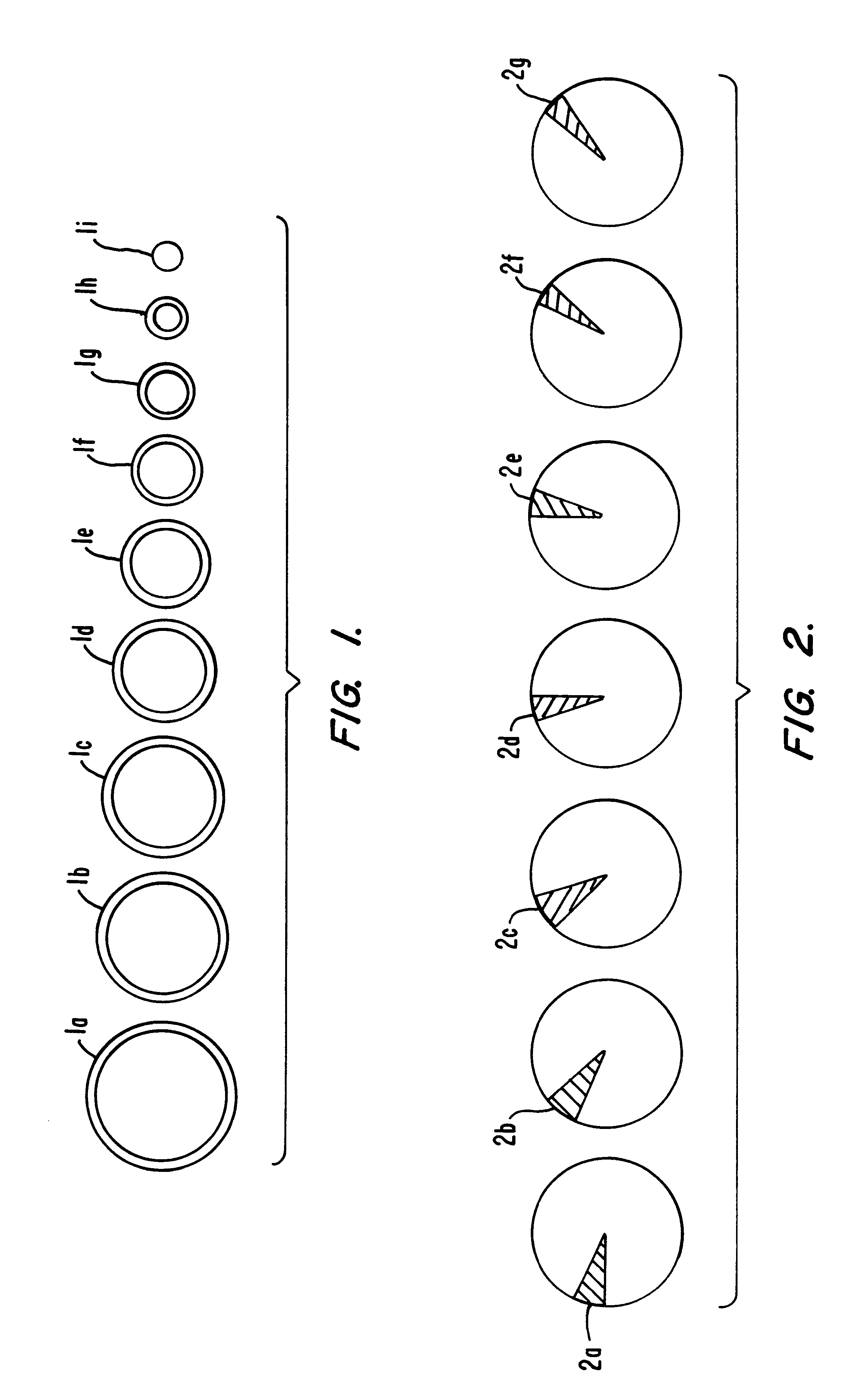
Referring now to FIG. 1, the methods and systems of the present invention will preferably employ a plurality of annular beam geometries as illustrated in FIG. 1. Most simply, successive rings 1a-1i may be projected onto the corneal tissue, where the outer diameter of each successive beam (e.g., 1b) is equal to the inner diameter of the previous beam (e.g., 1a). The final beam 1i will then cover the entire opening from the previous beam 1h. While it will usually be preferred to use a series of such successive, non-overlapping annular beams, it will also be possible to employ beams which overlap in a predictable manner so that the total dosage of ablative light energy to any point on the cornea can be controlled. It may also be possible to employ annular beam shapes that are elliptical, or having some other non-circular peripheral geometry.

As an alternative to the annular beam geometry shown in FIG. 1, the methods and systems of the present invention could project pie-shaped beams 2a-...


PUM


Abstract

A method for laser treatment of the eye using one or more diffractive optical elements for producing unique treatment segments within an ablation zone on the eye. The treatment segments may be annular, pie-shaped, or have other geometries or patterns selected to apply energy in a particular manner, usually in a non-overlapping manner so that energy dosages can be precisely controlled. In a first embodiment of the method, a single diffractive optical element is used and a beam expander expands or converges the beam to achieve the different treatment segments. In a second embodiment, a plurality of diffractive optical elements are used, each of which produces a single treatment segment.

Description

1. Field of the InventionThe present invention relates generally to medical systems and methods. More particularly, the present invention relates to the use of diffractive optics for generating successive patterns of light energy for ablating corneal or epithelial tissue.Photorefractive keratectomy (PRK) and phototherapeutic keratectomy (PTK) employ optical beam delivery systems for directing laser energy to a patient's eye in order to selectively ablate corneal tissue to reform the shape of the cornea and improve vision. All present commercial systems employ excimer lasers, where the beams from the lasers are spatially and temporally integrated in order to form a beam having uniform characteristics. In particular, the beams are integrated in order to display a flat intensity profile over a circular target region, often referred to as a "top hat" profile.Once such uniformly integrated beams are achieved, they may be used in different ways in order to effect corneal ablation. In a fi...

Claims


Application Information

Patent Timeline
Patent Type & Authority Patents(United States)
IPC IPC(8): A61F9/007A61F9/01G02B5/18A61B18/20G02B27/09
CPCA61F9/008A61F9/00804A61F9/00817A61F2009/00844A61F2009/00872
Inventor LEMBERG, VLADIMIR
Owner AMO MFG USA INC
Why Eureka
Try Eureka