
Treating instrument for endoscope

a technology for treating instruments and endoscopes, applied in the field of treating instruments, can solve problems such as bleeding from the cut end of the mucous membrane surface, bleeding from the hole opening after the needle, and bleeding from the hole itsel

Inactive Publication Date: 2001-02-27
ASAHI KOGAKU KOGYO KK
View PDF12 Cites 77 Cited by
  • Summary
  • Abstract
  • Description
  • Claims
  • Application Information

AI Technical Summary

Problems solved by technology

When such a syringe for an endoscope is used to give an injection into the mucous membrane in a body cavity, there may be bleeding from a hole opening after the needle has been pulled out.
In the case of removal of a polyp with a high-frequency snare, there may also be bleeding from the cut end of the mucous membrane surface.
In such a case, if a large amount of blood is lost through the bleeding because the blood vessel as a bleeding source is thick, the bleeding itself is dangerous.
Even when the amount of blood lost is not so large, as the time proceeds, the endoscopic observation may become impossible to perform due to the bleeding.
In such a case, it is difficult to continue the endoscopic examination.

Method used


Image

  • Treating instrument for endoscope
  • Treating instrument for endoscope
  • Treating instrument for endoscope

Examples


second embodiment

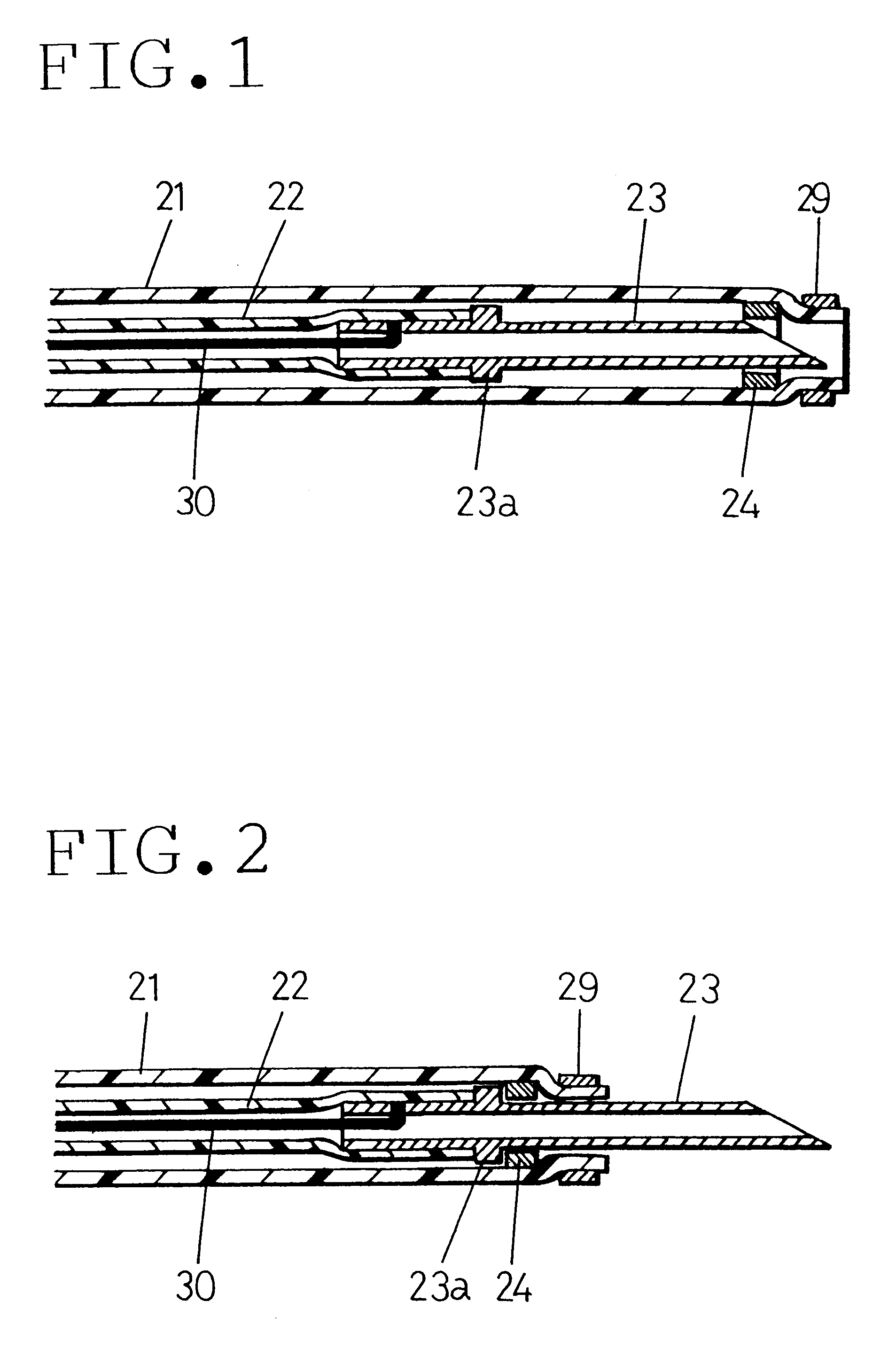
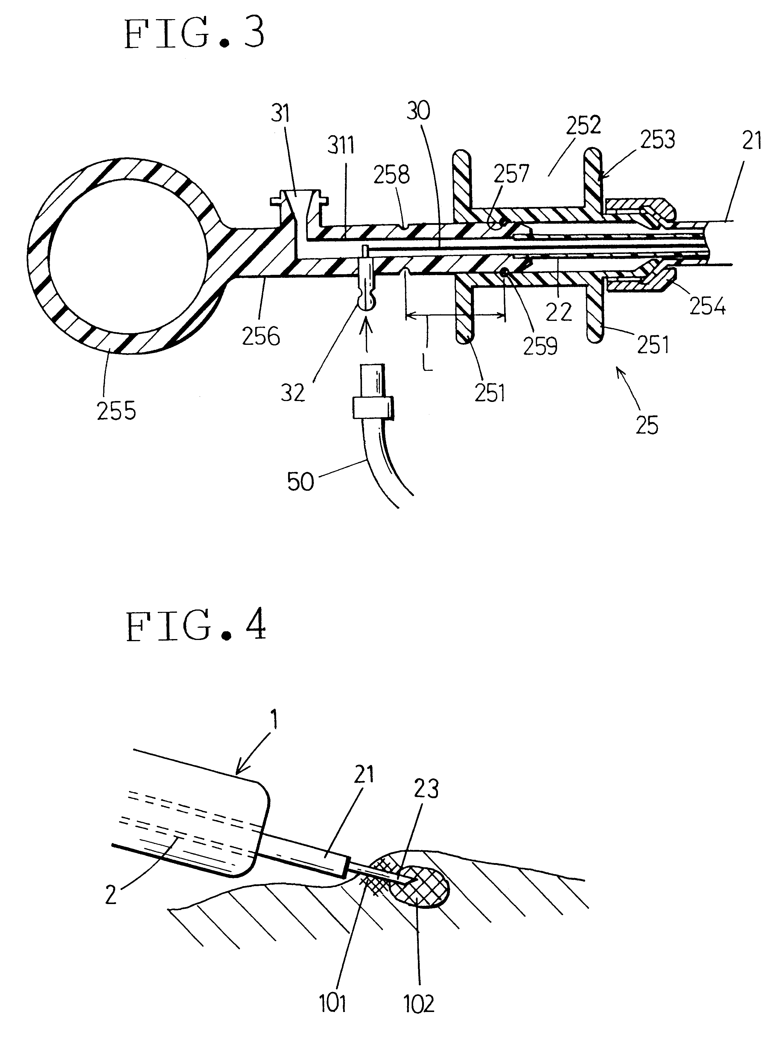
FIG. 5 shows a syringe for an endoscope according to the present invention. The fluid transfer tube 22 and the needle 23 are integrally formed from a thin tube of an electrically conductive metallic material such as a titanium alloy, a stainless steel or a super elastic alloy, e.g. a nickel-titanium alloy. The fluid transfer tube 22 per se is used as an electrically conductive material that carries a high-frequency electric current, thereby simplifying the structure.

The fluid transfer tube 22 has a diameter of the order of from 1 millimeter to 2 millimeters. Therefore, reducing the wall thickness of the fluid transfer tube 22 makes it possible to obtain flexibility that enables the fluid transfer tube 22 to be removably inserted into the instrument-inserting channel of the endoscope. The proximal end of the fluid transfer tube 22 is connected directly to the connecting terminal 32. The arrangement of the rest of the second embodiment is the same as that in the first embodiment.

third embodiment

FIGS. 6 and 7 show a syringe for an endoscope according to the present invention. FIG. 6 shows the syringe in a state where a needle 23 projects from the distal end of a sheath 11. FIG. 7 shows the syringe in a state where the needle 23 is withdrawn into the sheath 11.

The sheath 11 in this embodiment has a coil pipe 11a formed by helically close-winding an electrically conductive metal wire, e.g. a stainless steel wire, with a uniform diameter. The outer surface of the coil pipe 11a is covered with a flexible electrically insulating tube 11b such as a tetrafluoroethylene resin tube.

A high-frequency electrode 12 is secured to the distal end of the sheath 11 in such a manner that the electrode 12 is exposed at the whole distal end surface of the sheath 11. The high-frequency electrode 12 is made of an electrically conductive metal, e.g. a stainless steel. The high-frequency electrode 12 is connected to the distal end portion of the coil pipe 11a by silver brazing or soldering. Thus, t...


PUM


Abstract

A flexible sheath is removably inserted into an instrument-inserting channel of an endoscope. A treating member for applying a treatment to mucous membrane in a body cavity is projected from and withdrawn into the distal end of the sheath by an operation conducted at the proximal end of the sheath. An exposed electrode is provided at the distal end surface of the sheath. An electrically conductive member extending through the sheath is electrically connected at a distal end thereof to the electrode and at a proximal end thereof to a high-frequency power supply at the proximal end of the sheath.

Description

The present disclosure relates to subject matter contained in Japanese Patent Application No. 9-283212 (filed on Oct. 16, 1997) and Japanese Patent Application No. 9-283213 (filed on Oct. 16, 1997), which are expressly incorporated herein by reference in their entireties.1. Field of the InventionThe present invention relates to a treating instrument used through an instrument-inserting channel of an endoscope.2. Description of the Prior ArtThere are various instruments used with endoscopes. Syringes are used, for example, to inject a liquid medicine into the mucous membrane in a body cavity. High-frequency snares are used, for example, to excise polyps from the mucous membrane surface. These instruments are arranged such that a treating member, i.e. a syringe needle or a snare wire, used to apply a treatment to the mucous membrane in the body cavity projects from and withdraws into the distal end of a sheath removably inserted into an instrument-inserting channel of an endoscope.Whe...

Claims


Application Information

Patent Timeline
IPC IPC(8): A61B18/14
CPCA61B18/1477A61B2018/00196A61B2018/1253A61B2018/1425
Inventor OUCHI, TERUO
Owner ASAHI KOGAKU KOGYO KK
Learn More