
Seal for electrochromic devices

a technology of electrochromic devices and seals, applied in non-linear optics, instruments, optics, etc., can solve problems such as difficult placement of thin metal layers on the second or third surface, cte mismatch problems, and difficulty in ensuring adequate seal integrity, so as to improve the adhesion of the seal member 116

Inactive Publication Date: 2001-02-27
GENTEX CORP
View PDF11 Cites 66 Cited by
  • Summary
  • Abstract
  • Description
  • Claims
  • Application Information

AI Technical Summary

Benefits of technology

It is yet a further object of the present invention is to provide an electrochromic rearview mirror for motor vehicles incorporating a seal that has improved adhesion to a third surface reflector / electrode.
If desired, an optional layer or layers of a color suppression material 130 may be deposited between transparent conductive material 128 and the second surface 112b to suppress the reflection of any unwanted portions of the electromagnetic spectrum.
Because of their excellent adhesion to glass, low oxygen permeability and good solvent resistance, epoxy-based organic resin sealing systems are preferred. These epoxy resin seals may be UV curing, such as described in U.S. Pat. No. 4,297,401, or thermally curing, such as with mixtures of liquid epoxy resin with liquid polyamide resin or dicyandiamide, or they can be homopolymerized. The organic sealing resin may contain fillers or thickeners to reduce flow and shrinkage such as fumed silica, silica, mica, clay, calcium carbonate, alumina, etc., and / or pigments to add color. Fillers pretreated with hydrophobic or silane surface treatments are preferred. Cured resin crosslink density can be controlled by use of mixtures of mono-functional, di-functional and multi-functional epoxy resins and curing agents. Additives such as silanes or titanates can be used to improve the seal's hydrolytic stability and spacers such as glass beads or rods can be used to control final seal thickness and substrate spacing. Suitable epoxy sealing resins for use in a perimeter seal member 116 include but are not limited to: "EPON RESIN" 813, 825, 826, 828, 830, 834, 862, 1001F, 1002F, 2012, DPS-155, 164, 1031, 1074, 58005, 58006, 58034, 58901, 871, 872 and DPL-862 available from Shell Chemical Co., Houston, Tex.; "ARALITE" GY 6010, GY 6020, CY 9579, GT 7071, XU 248, EPN 1139, EPN 1138, PY 307, ECN 1235, ECN 1273, ECN 1280, MT 0163, MY 720, MY 0500, MY 0510 and PT 810 available from Ciba Geigy, Hawthome, N.Y.; "D.E.R. " 331, 317, 361, 383, 661, 662, 667, 732, 736, "D.E.N." 431, 438, 439 and 444 available from Dow Chemical Co., Midland, Mich.
In one embodiment of the present invention, this second region should be compatible with, but need not include groups that are reactive with, the seal member 116. In this embodiment, the first region will interact with the layer of metal and the second region may be an organic moiety that is compatible with the epoxy seal member and extend away from the reflector / electrode 120 and into the seal member 116 such that when the epoxy cures the part of the organic moiety that extends into the seal member 116 and anchors the seal member and therefore improves the adhesion of the seal member 116 to the layer of metal.
In another embodiment of the present invention, the second region of the adhesion promoter should be organic and contain any moiety capable of reacting with an epoxide group, or with the epoxy polymer, such as through the secondary hydroxide group present therein. This list may include at least one of the following reactive groups: acetals, acetoacetates, nitriles, alkynes, acid anhydrides, acyl halides, alcohols, aldehydes, alkyl halides, alkyl hydroperoxides, amides, primary, secondary and tertiary amines, 2-aminothiols, aryl dichloroarsines, carbamyl chloride, carboxylic acids, cyanates, cyanoacetates, epoxides, ethylene imines, halohydrins, ketones, malonates, metal alkoxides, phenols, phosphines, alkyl phosphonic acids, phthalimides, alkyl silicon halides, siloxanes, thiocyanates, thioacids, thiols and thionyl chlorides. In this case the second region actually bonds with the seal member 116 and therefore improves the adhesion of the seal member 116 to the reflector / electrode.
For thermally cured systems, it is desirable to cure the seal member 116 above its ultimate glass transition temperature in order to achieve full cure in a minimum amount of time. As a general rule, the glass transition temperature of the seal member should be well above the maximum expected service temperature for an application. Thus, for seal members used in automotive or outdoor architectural applications, adhesive glass transition temperatures of 130 to 150 degrees Celsius or above are not uncommon. If, however, the seal member 116 and substrates are heated to above these temperatures and then cooled, stress due to thermal mismatch between the seal member 116 and substrate(s) begins to develop when the temperature drops below the glass transition temperature of the seal member and the seal member becomes more rigid. At room temperature the stress induced by 125 degrees Celsius cooling the electrochromic device containing glass elements (112 and 114) and a seal member 116 having mismatched CTFs can be substantial. If the adhesive strength between the substrates and seal member 116 is compromised by contamination or other causes, premature bond failure can occur. The higher stress levels created by the CTE mismatch increase the likelihood that bond failure will occur.

Problems solved by technology

This may cause problems ensuring adequate seal integrity over long periods of time because of the difference in the coefficient of thermal expansion (CTE) between the seal and the glass transparent elements.
This CTE mismatch problem is pronounced (with or without spacer beads) for electrochromic devices that are operated over a wide temperature range, such as architectural windows and automotive windows.
In practice, however, placing the thin metal layer on the second or third surface, or the reflector on the third surface, has been difficult.
One reason for this difficulty is that the seal used to bond the two pieces of glass together and hold them in a spaced-apart relationship does not always bond well with certain metals, especially reflective and noble metals.

Method used


Image

  • Seal for electrochromic devices
  • Seal for electrochromic devices
  • Seal for electrochromic devices

Examples


example 2

Electrochromic elements were made by the same methods as example 1 with the following modifications:

The silver of the 3.sup.rd surface reflector was replaced with one of the following three alloys:

3% palladium in silver (to be designated 3% Pd in Ag)

6% platinum in silver (to be designated 6% Pt in Ag)

15% gold in silver (to be designated 15% Au in Ag)

The epoxy resin systems were modified as follows: The base resin was comprised of 93% by weight D.E.N. 431 and 7% of a different surface modified fumed silica (TS 720 from Cabot) that has been vacuum mixed in a planetary mixer prior to the addition of other materials. As per the final resins in example 1 the final resins of example 2 all contain (by weight) 1% 137 um glass beads, 1 / 2% aminosilane (A-1120) and 36% amine curing agent (Ancamine 2049).

The differences in the final resins of example 2 are as follows:

Resin 2A-no other additives

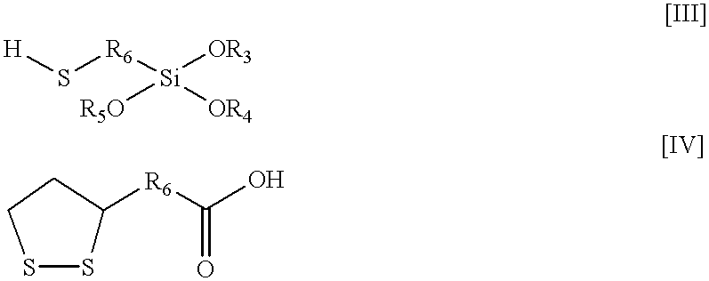
Resin 2B-1 / 2% (by weight) mercaptopropyl trimethoxy silane

Resin 2C-2% thioctic acid

Resin 2D-2% DeGussa...


PUM

PropertyMeasurementUnit
diameteraaaaaaaaaa
wavelengthsaaaaaaaaaa
temperatureaaaaaaaaaa

Abstract

An improved seal member is provided as a part of an electrochromic device to bond two glass elements together in a spaced-apart relationship. In one embodiment the seal member provides improved adhesion to a reflector / electrode on the third surface of an electrochromic mirror, or to a layer of metal on the second or third surface for an electrochromic light filter. This seal member comprises a mixture of an organic resin scaling system and an adhesion promoter, where the adhesion promotor comprises a first and a second region, where the first region interacts with the reflector / electrode or the metal layer, and a second region that interacts with the organic resin sealing system, and may even chemically react with the organic resin sealing system. In another embodiment the seal member is provided with a coefficient of thermal expansion that is closer to glass than a standard epoxy sealing system.

Description

This invention relates to electrochromic devices and, more particularly, to electrochromic light filters or windows, as well as electrochromic and rearview mirrors having an improved seal member.Heretofore, devices of reversibly variable transmittance to electromagnetic radiation have been proposed as the variable transmittance element in variable transmittance lightfilters, variable reflectance mirrors, and display devices which employ such lightfilters or mirrors in conveying information. These variable transmittance light filters have included windows. One commercially available device is an electrochromic mirror for motor vehicles. These electrochromic mirrors change from the full reflectance mode (day) to the partial reflectance mode(s) (night) for glare-protection purposes from light emanating from the headlights of vehicles approaching from the rear. Among such devices are those wherein the transmittance is varied by thermochromic, photochromic, or electro-optic (e.g., liquid...

Claims


Application Information

Patent Timeline
Patent Type & Authority Patents(United States)
IPC IPC(8): G02F1/01G02F1/161G02F1/15
CPCG02F1/161
Inventor ANDERSON, JOHN S.TONAR, WILLIAM L.ASH, KEVIN L.GUARR, THOMAS F.
Owner GENTEX CORP
Learn More