Two-mode demodulating apparatus

a demodulating apparatus and two-mode technology, applied in the direction of phase-modulated carrier systems, digital transmission, transmission monitoring, etc., can solve the problems of insufficient number of base stations to which such digital communication systems having a higher frequency utilization efficiency are connected, and the interruption of lines is often difficult to achiev

Inactive Publication Date: 2001-02-27
FUJITSU LTD
View PDF5 Cites 52 Cited by
  • Summary
  • Abstract
  • Description
  • Claims
  • Application Information

AI Technical Summary

Problems solved by technology

Shortage of frequency bands usable as transmission frequencies with an increase of subscribers is showing up in recent radio communication system, which causes troubles in communication such that a telephone line is often interrupted or a telephone communication becomes broken, etc.
However, the number of base stations to which such digital communication system having a higher efficiency of frequency utilization is still insufficient and an area in which the digital communication can be used is limited, as compared with analog communication systems using known linear modulating systems.
If the above two-mode receiving apparatus is applied to a mobile terminal in a mobile communication system, for example, it is difficult to meet a strong demand for portability or compactness of the terminal.
On the other hand, the non-linear modulated wave passes through a different band according to a type of system (analog communication system) such as AMPS, TACS, NAMPS, NTACS or the like so that it is difficult to versatilely use hardware to an applied non-linear modulated wave system.
Accordingly, it is necessary to change or switch the filter to be used according to a required non-linear modulation system, besides it is difficult to reduce the cost or improve the reliability when the apparatus including the non-linear receiving filters is formed into an LSI (Large-Scale Integrated circuit).
In addition, it is impossible to completely eliminate steady-state frequency deviation in the quasi-synchronous detection system so that it is difficult to perform a demodulating process corresponding to each of various non-linear modulated waves (particularly, NAMPS, NTACS, etc.).
In this case, an AFC (automatic frequency control) operation, which is not required originally in the non-linear receiving circuit, is required in order to eliminate the above steady-state frequency deviation, besides the A / D converters 116I, 116Q, 126I and 126Q are required to be provided separately for the linear modulated wave and the non-linear modulated wave, which causes an increase in power consumption.

Method used


Image

  • Two-mode demodulating apparatus
  • Two-mode demodulating apparatus
  • Two-mode demodulating apparatus

Examples


first embodiment

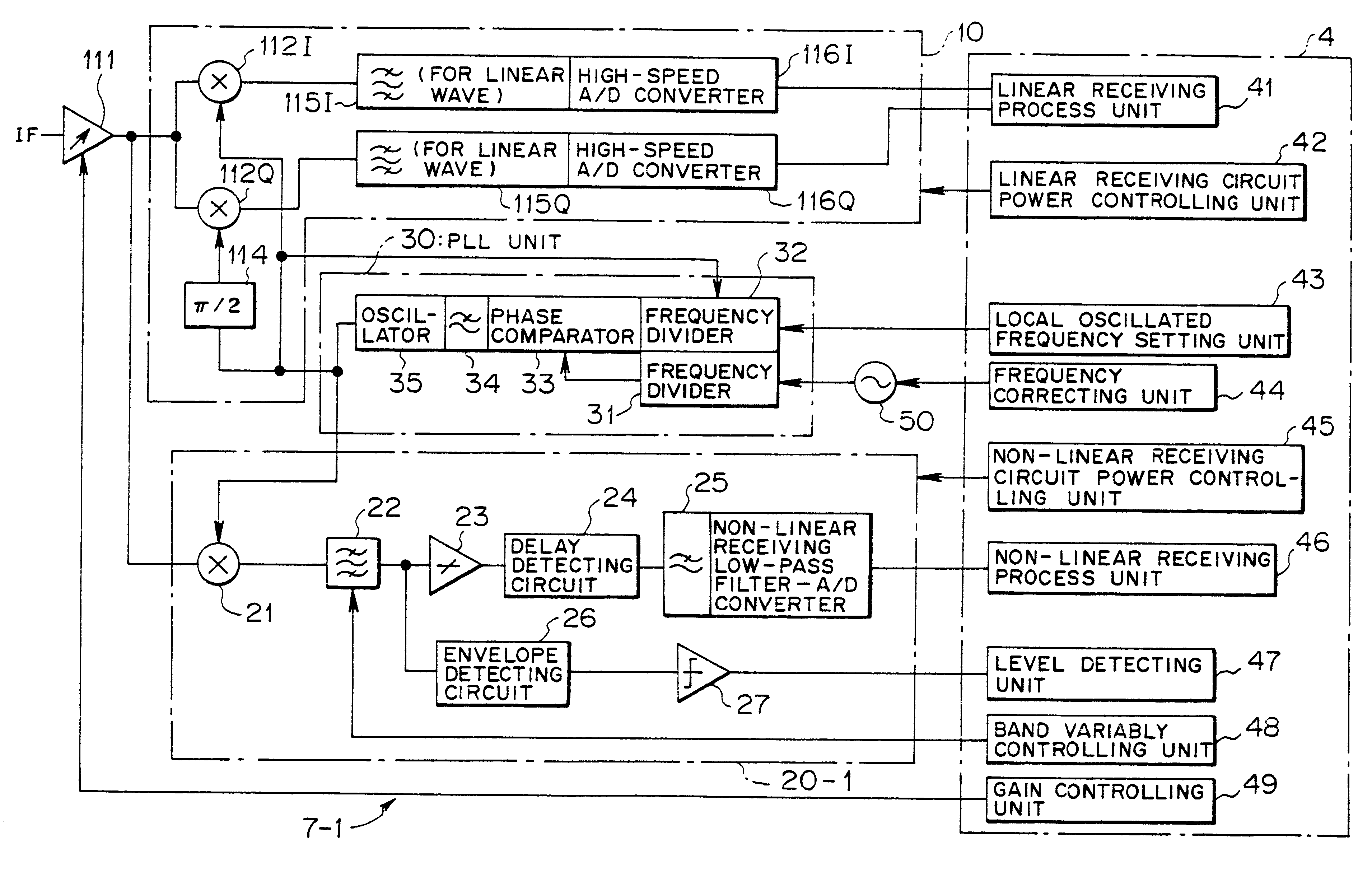
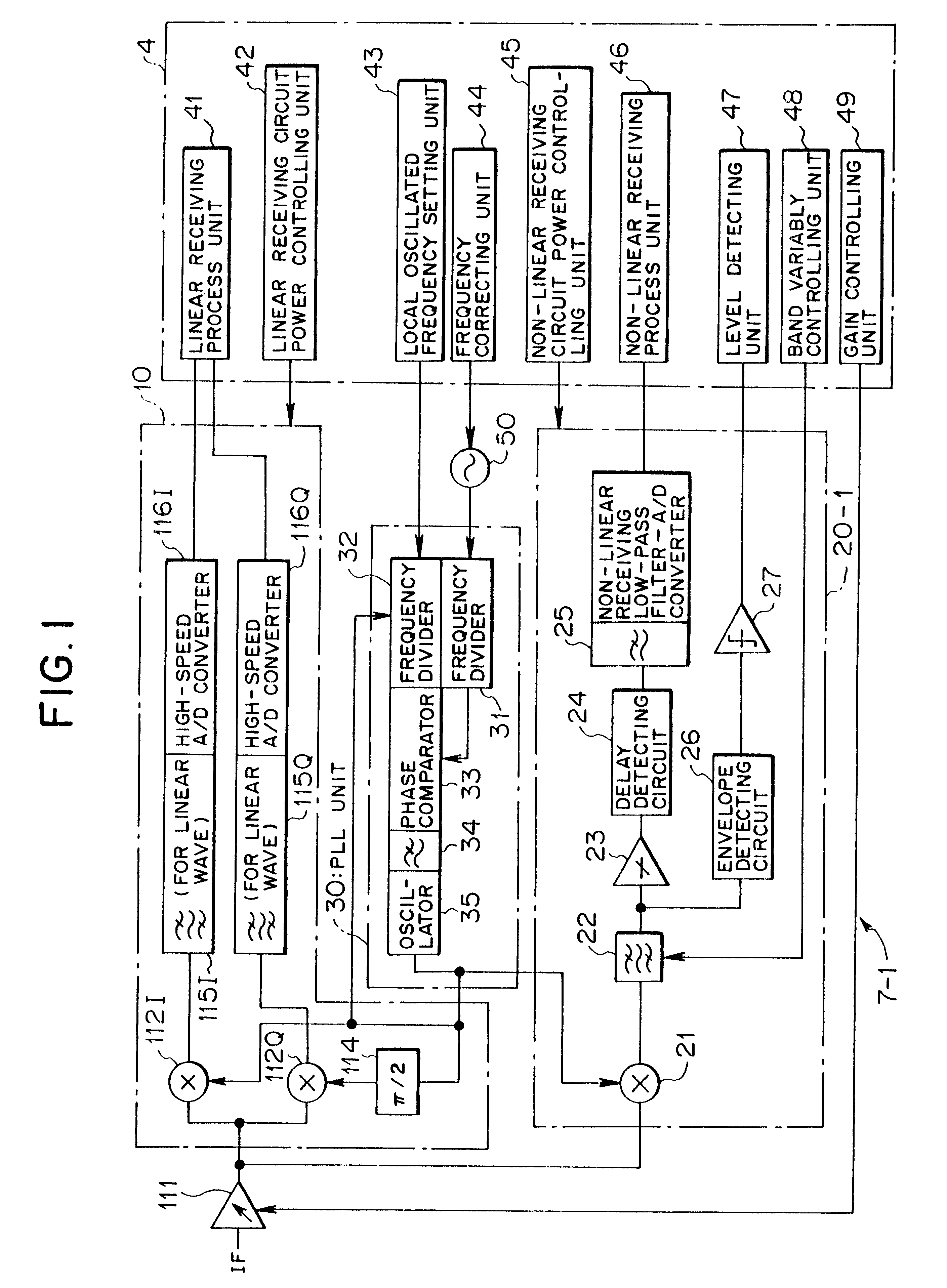
FIG. 1 is a block diagram showing a two-mode demodulating apparatus according to this invention. A two-mode demodulating apparatus 7-1 shown in FIG. 1 is applicable to a linear / non-linear receiving process unit 3 and a digital processing unit 4 as a received signal processing system of a mobile station 1 in a mobile communication system as shown in FIG. 2, for example.

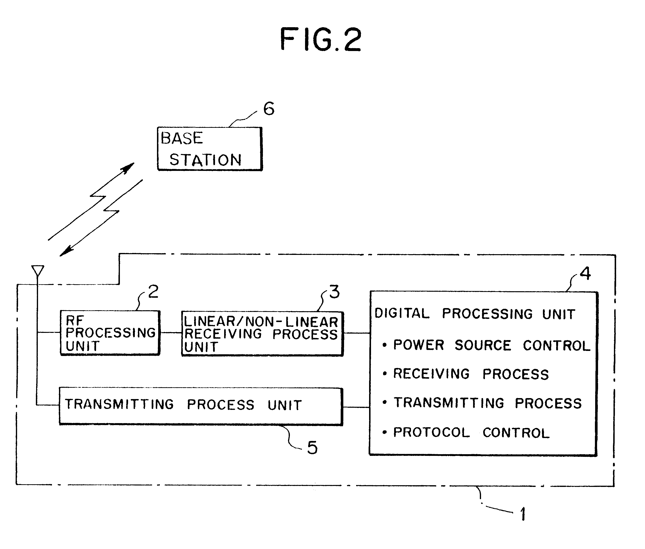
The mobile station 1 shown in FIG. 2 has an RF processing unit 2 and the linear / non-linear receiving process unit 3 as a receiving system, the digital processing unit 4, and a transmitting process unit 5, thereby exchanging a linear modulated wave in a digital communication system or a non-linear modulated wave in an analog communication system with a base station 6.

The RF processing unit 2 performs frequency conversion on a received signal (RF signal) in a high frequency, and outputs an intermediate frequency signal (IF signal) as the received signal. The linear / non-linear reception processing unit 3 demodulates a lin...

second embodiment

(b) Description of a Second Embodiment

FIG. 6 is a block diagram showing a two-mode demodulating apparatus according to a second embodiment of this invention. A two-mode demodulating apparatus 7-2 shown in FIG. 6 has a non-linear reception demodulating circuit 20-2 with a structure different from that of the non-linear reception demodulating circuit 20-1 of the above-mentioned two-mode demodulating apparatus 7-1 according to the first embodiment.

In the non-linear reception demodulating circuit 20-2 according to the second embodiment, there is provided a frequency measuring circuit 28 instead of the delay detecting circuit 24 and the non-linear receiving low-pass filter-A / D converter 25 as the non-linear reception demodulating process unit, the frequency measuring circuit 28 demodulating a received signal.

Namely, the frequency measuring circuit 28 measures a frequency of a signal, which has been subjected to band limit such as to be adapted to a baseband signal band in a desired non-l...

third embodiment

(c) Description of a Third Embodiment

FIG. 9 is a block diagram showing a two-mode demodulating apparatus according to a third embodiment of this invention. A two-mode demodulating apparatus 7-3 shown in FIG. 9 has a non-linear reception demodulating circuit 20-3 having a different structure, as compared with the above two-mode demodulating apparatus 7-1 according to the first embodiment.

Namely, the non-linear reception demodulating circuit 20-3 according to the third embodiment has a down sampling-A / D converter (analog-to-digital converting circuit) 29 receiving an output from the band-limit filter 22 to perform a down sampling operation, instead of the delay detecting circuit 24, the non-linear receiving low-pass filer-A / D converter 25 as the non-linear reception demodulating process unit. The down-sampling-A / D converter 29 can demodulate the received signal.

The down sampling-A / D converter 29 has, in detail, sample-and-hold circuits 29A and 29B in two systems, a circuit changing sw...


PUM


Abstract

A two-mode demodulating apparatus for use in a radio terminal in a mobile communication system has a linear reception demodulating circuit and a non-linear reception demodulating circuit which can be selectively operated by selecting a mode. The non-linear reception demodulating circuit has a second frequency converting unit for frequency-converting a received signal into a low-frequency signal, a variable-band filtering unit for allowing a signal in a desired band contained in an output of the second frequency converting unit to pass therethrough, and a non-linear reception demodulating process unit for performing a non-linear reception demodulating process on an output from the filtering unit, thereby receiving and demodulating a linear modulated wave and a non-linear modulated wave while suppressing increases of the circuit scale and the power consumption, and generalizing a hardware structure for an applied non-linear modulating system.

Description

(1) Field of the InventionThe present invention relates to a two-mode demodulating apparatus suitable for use in a radio terminal in, for example, a mobile communication system.(2) Description of Related ArtShortage of frequency bands usable as transmission frequencies with an increase of subscribers is showing up in recent radio communication system, which causes troubles in communication such that a telephone line is often interrupted or a telephone communication becomes broken, etc. In order to avoid such troubles in the communication, there have been developed and operated various techniques of improving efficiency of frequency utilization as countermeasures.A digital communication system having a higher efficiency of frequency utilization using a linear modulation system comes to be used, for instance. However, the number of base stations to which such digital communication system having a higher efficiency of frequency utilization is still insufficient and an area in which the...

Claims


Application Information

Patent Timeline
Patent Type & Authority Patents(United States)
IPC IPC(8): H04L27/233H04L27/227H04L27/00H04B1/26
CPCH04L27/2273H04L27/2332H04L2027/0055H04L2027/0057
Inventor MAEDA, MITSUNORI
Owner FUJITSU LTD
Why Eureka
Try Eureka