Computer enclosure cooling unit

a cooling unit and computer enclosure technology, applied in the direction of electrical apparatus casings/cabinets/drawers, semiconductor/solid-state device details, instruments, etc., can solve the problems of inability to meet the standards set for computer drive bays, failure to address the need for focused cooling created by the high operating temperature of currently available high-density semiconductor devices, and high cost of this approach

Inactive Publication Date: 2001-03-06
THERMAL PARTNERS LLC +1
View PDF11 Cites 102 Cited by
  • Summary
  • Abstract
  • Description
  • Claims
  • Application Information

AI Technical Summary

Problems solved by technology

However, all such prior art blower and / or fan systems encounter a problem, the heat transfer efficiency out of the enclosure is limited by the temperature differential between the air inside the computer enclosure and the air in the room ambient.
However, transfer of heat out of the entirety of the enclosure, rather than just specific semiconductor devices is need for optimal cooling of the computer enclosure; in that the density of switches within a specific semiconductor device is a source of excessive heating and that the density of devices, both electronic and electrical, within the computer enclosure is yet another source of excessive heating.
However, even the conformance of the air circulation system to the standards set for computer drive bays fails to address the need for focused cooling created by the high operating temperatures of currently available high-density semiconductor devices.
The expense of this approach is often prohibitive, as is the physical size and placement of the refrigeration system components.

Method used


Image

  • Computer enclosure cooling unit
  • Computer enclosure cooling unit
  • Computer enclosure cooling unit

Examples


second embodiment

Heat flow communication between the cooling fluid within the cooling fluid cooling unit 34 and the heat conductive material comprising the lower surface of the enclosure air cooling unit 26 acts to provide a cool surface for heat exchange with the air circulating within the enclosure air cooling unit 26. The preferred embodiment, created with cost considerations foremost in mind, utilizes simple heat conductive sheet metal for the surfaces between the enclosure air cooling unit 26 and the cooling fluid cooling unit 34, between the cooling fluid cooling unit 34 and the Peltier plate 30, between the Peltier plate 30 and the ambient air heat exchanger 60, and for the construction of the computer enclosure cooling unit housing 1 which serves as the outer walls of all sub-units as well as the upper surface of the enclosure air cooling unit 26 and the lower surface of the ambient air heat exchanger 60. This construction of the computer enclosure cooling unit housing 1 from heat conductive...

third embodiment

Cooling of the air within the enclosure air cooling unit 26, whether configured as in the preferred embodiment or in the third embodiment, creates a condensate on the cooled surface(s) where the heat exchange with the circulating air takes place. In the preferred embodiment the lower surface of the enclosure air cooling unit 26 is beveled or sloped toward a condensate drain 37. The condensate drain 37 comprises a tube having its upper end opening in the lower surface of the enclosure air cooling unit 26 and its lower end opening in the upper surface of the ambient air heat exchanger 60. The condensate drain 37 is ideally comprised of non-heat conductive materials, alternatively, the condensate drain 37 may be heat insulated from the heat conductive surfaces that it passes through. Freezing of the condensate within the tube comprising the condensate drain 37 as it passes through the upper surface of the Peltier plate 30 must be avoided. A yet third, and not as desirable, solution to ...

fourth embodiment

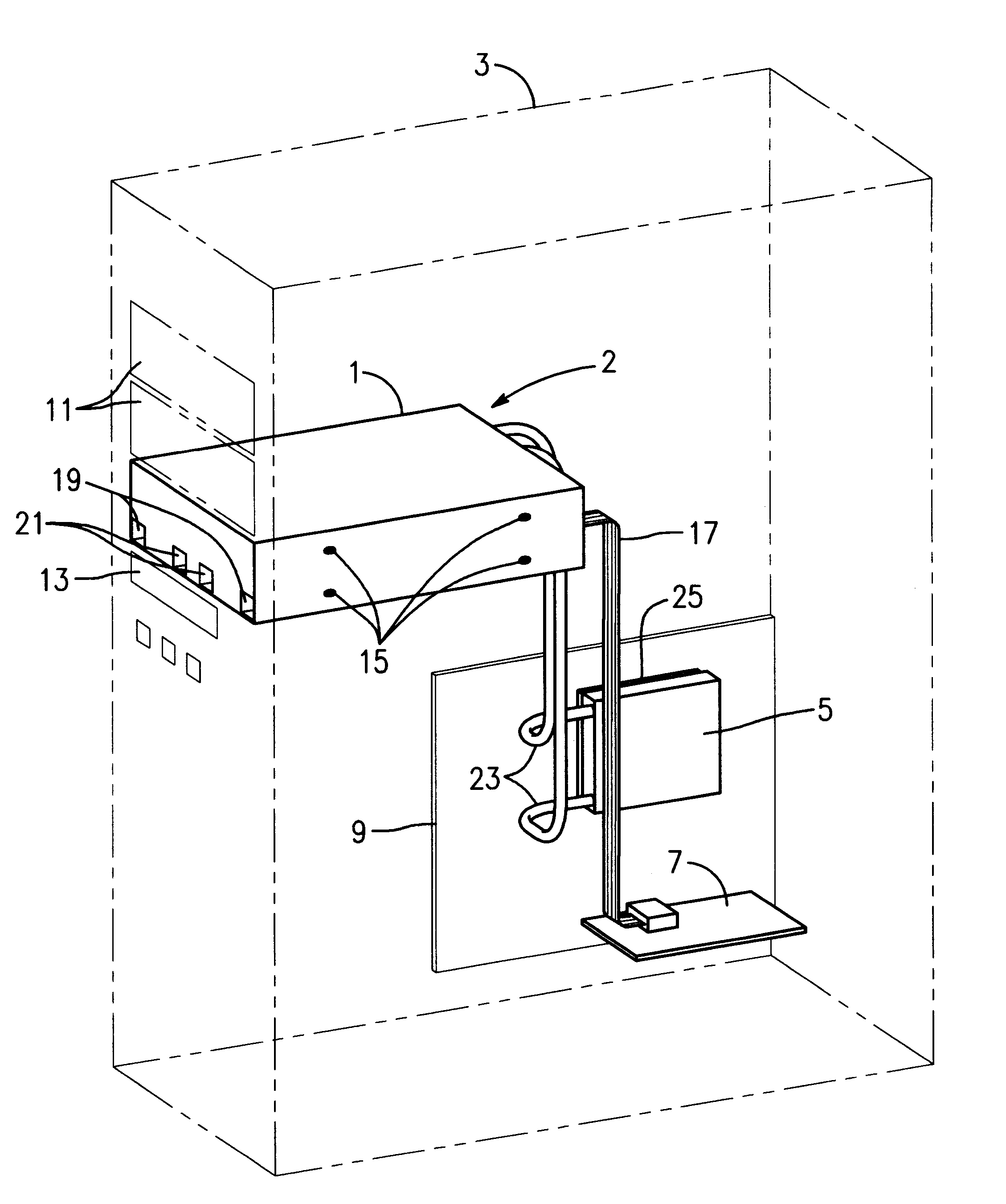
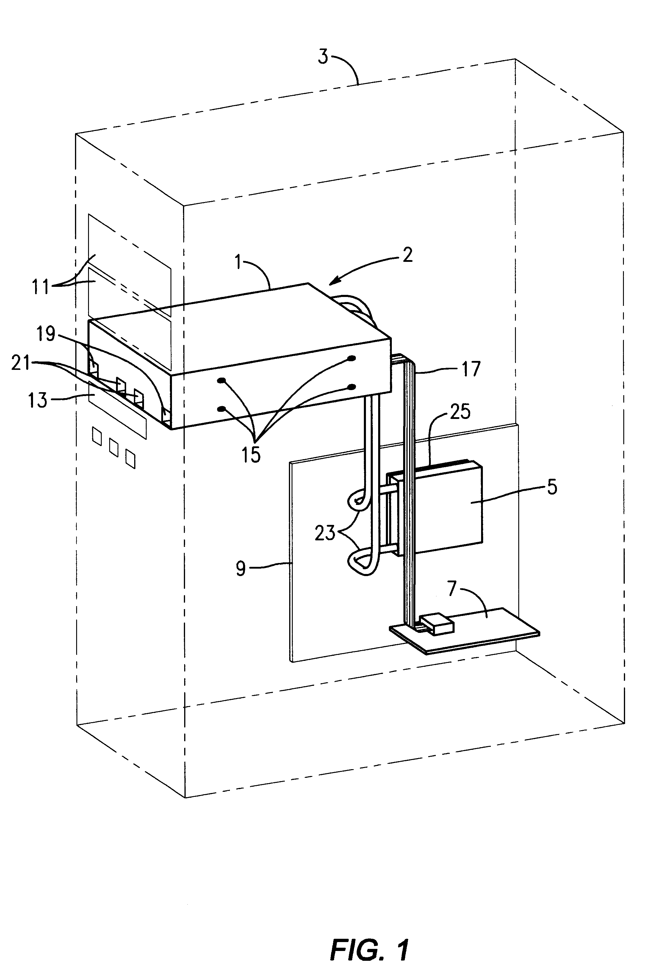
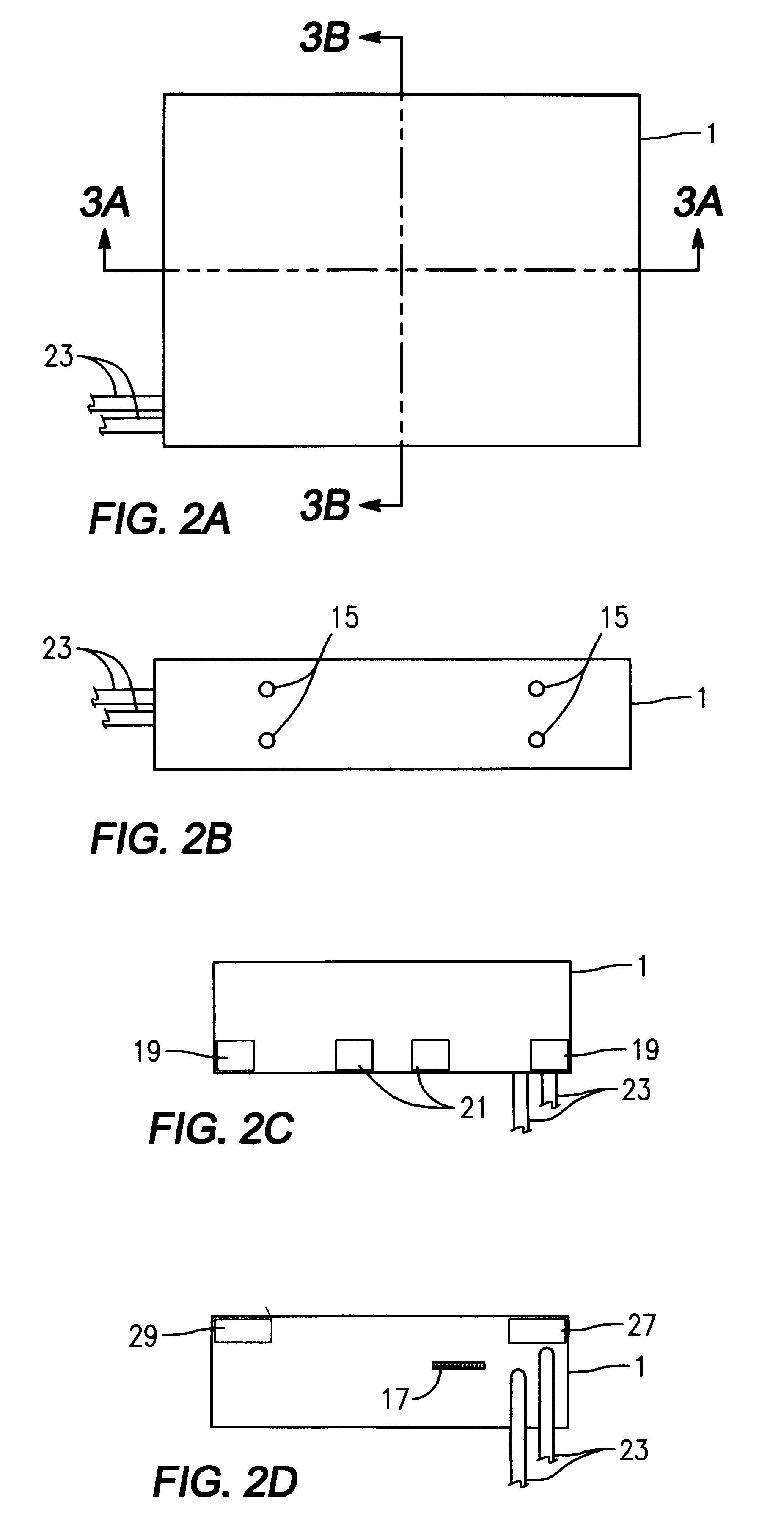
the instant invention provides that the air exhaust from the computer housing 3, having been cooled by the air exhaust from the enclosure air cooling unit air exhaust 29, is input to the ambient air heat exchanger air intake 19. Thus a single path for air flow from and to the ambient air within the room containing the computer housing 3 is established. Greater efficiency of heat exchange over the entirety of the computer enclosure cooling unit 2 can be achieved by the fourth embodiment, but at a cost of increased tubing or piping to contain the flow of air from the air exhaust of the enclosure air cooling unit 26 to the ambient air heat exchanger air intake 19.


PUM


Abstract

A computer enclosure cooling unit adapted to current dimensional standards which is capable of controlled cooling of individual semiconductor devices as well as of the air circulated within the computer housing. The disclosed invention utilizes Peltier devices, a controller unit, both liquid and gaseous heat exchangers, and low cost construction methods to provide a compact, effective computer enclosure cooling system meeting the cooling needs of current high-speed, heat producing computer systems and components.

Description

a. Field of the InventionThe present invention is related generally to the field of computer enclosure cooling units. A substantial problem exists in keeping computer enclosures cooled. Typically a computer enclosure houses numerous semiconductor units, certain motorized units, and power supplies, all of which tend to be in varying degrees inefficient and therefore heat producing. Semiconductor units typically have an optimal temperature operating range at or below room temperature (20 degrees Celsius). Most computer enclosures are air cooled with blowers or fans circulating air from the enclosure into the ambient of the room within which the computer enclosure is located.More particularly the present invention is related to computer enclosure cooling units that utilize Peltier devices to enhance heat transfer out of the computer enclosure into the air circulated into the room ambient. Peltier devices are well known for the transfer of heat through the device induced by electric cur...

Claims


Application Information

Patent Timeline
Patent Type & Authority Patents(United States)
IPC IPC(8): F25B21/02G06F1/20H01L23/38H01L23/34H01L23/467
CPCF25B21/02G06F1/20H01L23/38H01L23/467H01L2924/0002H01L2924/00
Inventor MACIAS, JOSE JAVIERSILVA, ROGELIO HERNANDEZ
Owner THERMAL PARTNERS LLC
Why Eureka
Try Eureka