Pressure regulating method and apparatus

a technology of pressure regulation and pressure conduit, which is applied in the direction of valve details, fluid pressure control, instruments, etc., can solve the problems of high percentage of kinetic energy of fluid (such as oil) being ultimately converted into heat, and the pressure in the pilot conduit (between the pilot valve and the regulating valve) cannot match the pressure of fluid in the constant-pressure conduit, etc., to achieve simple, compact and simple, reduce the effect of pilot pressur

Inactive Publication Date: 2001-03-06
LUK GETRIEBE SYST
View PDF14 Cites 5 Cited by
  • Summary
  • Abstract
  • Description
  • Claims
  • Application Information

AI Technical Summary

Benefits of technology

Another object of the invention is to provide a method which can be practiced without the generation of appreciable, noticeable or even any quantities of heat.
A further object of the invention is to provide a method which can be practiced by resorting to a relatively simple, compact and inexpensive apparatus.
An additional object of the invention is to provide a method which renders it possible to reduce the pilot pressure between the pilot valve and the regulating valve of the appparatus to a threshold value below that achievable by resorting to heretofore known methods.
Still another object of the invention is to provide an apparatus which can be utilized for the practice of the above outlined method and is designed in such a way that the afore described drawbacks of conventional apparatus can be avoided in a simple, effective and inexpensive manner.

Problems solved by technology

A drawback of heretofore known pressure regulating methods and apparatus of the just outlined character is that (for example, due to often unavoidable leakage of fluid from the pilot valve and / or from other parts of the apparatus), the pressure in the pilot conduit (between the pilot valve and the regulating valve) cannot match the pressure of fluid in the constant-pressure conduit.
A further drawback of the aforedescribed conventional pressure regulating apparatus is that, due to turbulence which develops in the fluid path in the region of the flow restrictor, at least a high percentage of kinetic energy of the fluid (such as oil) is ultimately converted into heat.

Method used


Image

  • Pressure regulating method and apparatus
  • Pressure regulating method and apparatus
  • Pressure regulating method and apparatus

Examples


Embodiment Construction

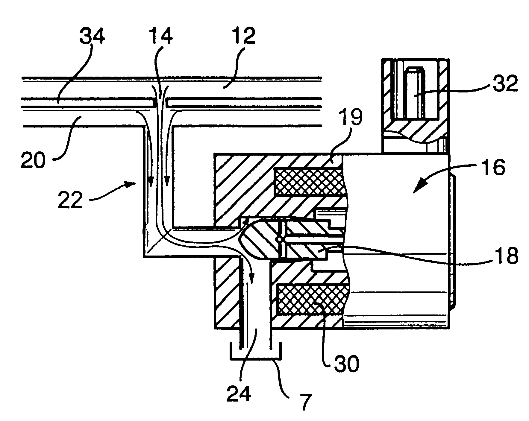
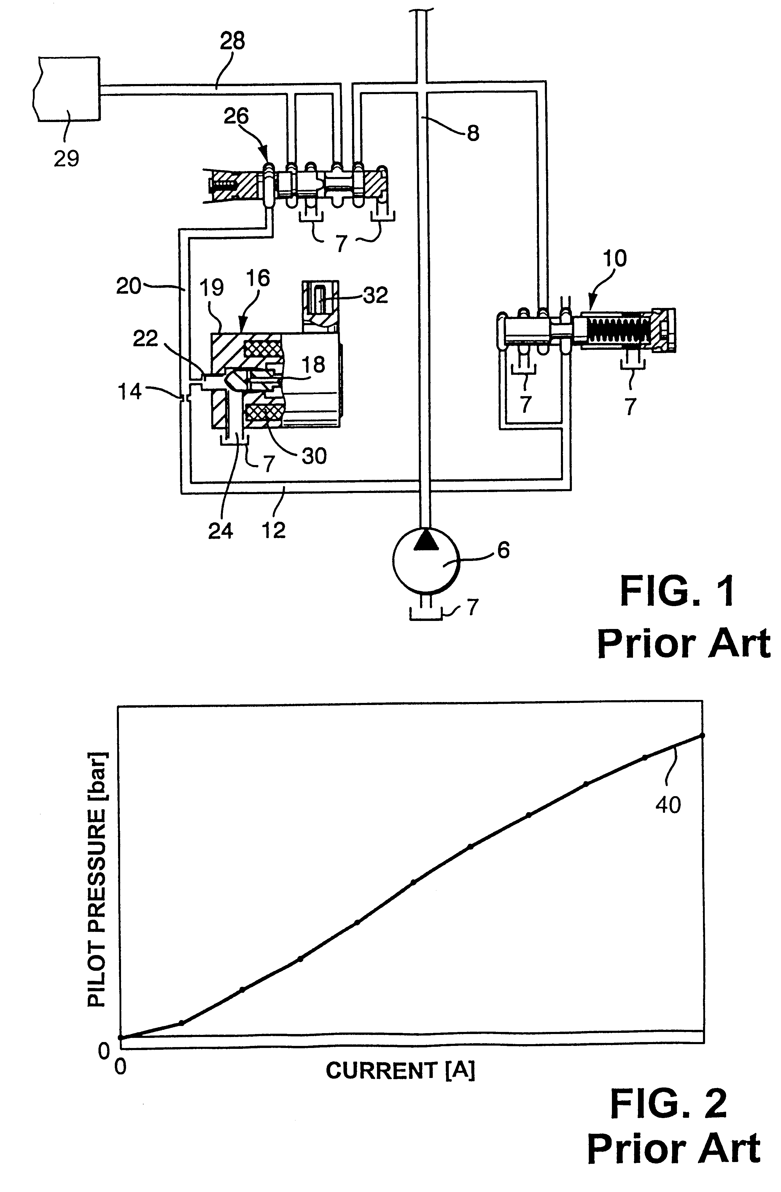
FIG. 1 shows certain component parts of a conventional apparatus which includes a pump 6 serving to draw hydraulic fluid (such as oil and hereinafter referred to as fluid) from a source 7, e.g., a sump. The outlet of the pump 6 delivers a stream of fluid into a main conduit 8 at a pressure which can exceed the pressure required in a control conduit 28 serving to deliver at least one stream of pressurized fluid to at least one inlet of a consumer 29, e.g., a continuously variable transmission (CVT) of the type disclosed in the commonly owned U.S. Pat. No. 5,667,448 or 5,674,155.

The main conduit 8 supplies pressurized fluid to an inlet of a constant-pressure valve 10 (this valve can be replaced with a pressure regulating valve, not shown) having an outlet connected with the inlet or intake end of a (first) constant-pressure conduit 12. The valve 10 supplies fluid at an at least substantially constant pressure. The discharge end or outlet of the constant-pressure conduit 12 delivers fl...


PUM


Abstract

The pressure of hydraulic fluid which is supplied to the continuously variable transmission in the power train of a motor vehicle is regulated by an apparatus wherein an adjustable pilot valve can receive fluid from a pilot conduit leading to a pressure reducing valve. The pilot conduit normally receives fluid from a further conduit, wherein the pressure of fluid is at least substantially constant, by way of a flow restrictor. A branch conduit serves to evacuate fluid from the pilot conduit into the pilot valve when the latter is at least partially open. The fluid-discharging end of the flow restrictor confronts the inlet of the branch conduit, and such inlet is narrowed to reduce the likelihood of turbulence developing in the fluid stream flowing from the pilot conduit, across the further conduit and into the inlet of the pilot valve.

Description

The present invention relates to improvements in pressure regulating methods and apparatus.It is often necessary to design a hydraulic control system in such a way that a regulating or control valve (e.g., a pressure reducing valve) is installed downstream of a pilot valve or servo valve (hereinafter called pilot valve). The latter serves to select fluid pressure in a (pilot) conduit which is connected with an inlet of the regulating valve. An outlet of the regulating valve serves to convey fluid to one or more consumers, e.g., to a so-called continuously variable transmission (CVT). Reference may be had, for example, to commonly owned U.S. Pat. No. 5,667,448 (granted Sep. 16, 1997 to Oswald Friedmann for "POWER TRAIN") and to commonly owned U.S. Pat. No. 5,674,155 (granted Oct. 7, 1997 to Dieter Otto et al. for "METHOD OF AND APPARATUS FOR TRANSMITTING TORQUE IN THE POWER TRAINS OF MOTOR VEHICLES"). The disclosures of the just enumerated US patents as well as of all other patents a...

Claims


Application Information

Patent Timeline
Patent Type & Authority Patents(United States)
IPC IPC(8): G05D16/16G05D16/20G05D16/00F15B11/028
CPCG05D16/2013G05D16/2093G05D16/024G05D16/2022G05D16/2097Y10T137/0396Y10T137/2278Y10T137/8659Y10T137/86614
Inventor KEMMNER, BENJAMINFRIETSCH, THOMASEIDLOTH, RAINER
Owner LUK GETRIEBE SYST
Why Eureka
Try Eureka