
Casing for noise attenuation in a rock drilling rig

a drilling rig and noise attenuation technology, which is applied in the direction of directional drilling, instruments, borehole/well accessories, etc., can solve the problems of inconvenience for those working on the site, affecting the progress of work, and affecting so as to prevent the noise generated during drilling, the degree of drilling equipment utilization can be raised, and the noise attenuation effect is convenient and abated.

Inactive Publication Date: 2001-03-13
SANDVIK INTELLECTUAL PROPERTY AB
View PDF19 Cites 37 Cited by
  • Summary
  • Abstract
  • Description
  • Claims
  • Application Information

AI Technical Summary

Benefits of technology

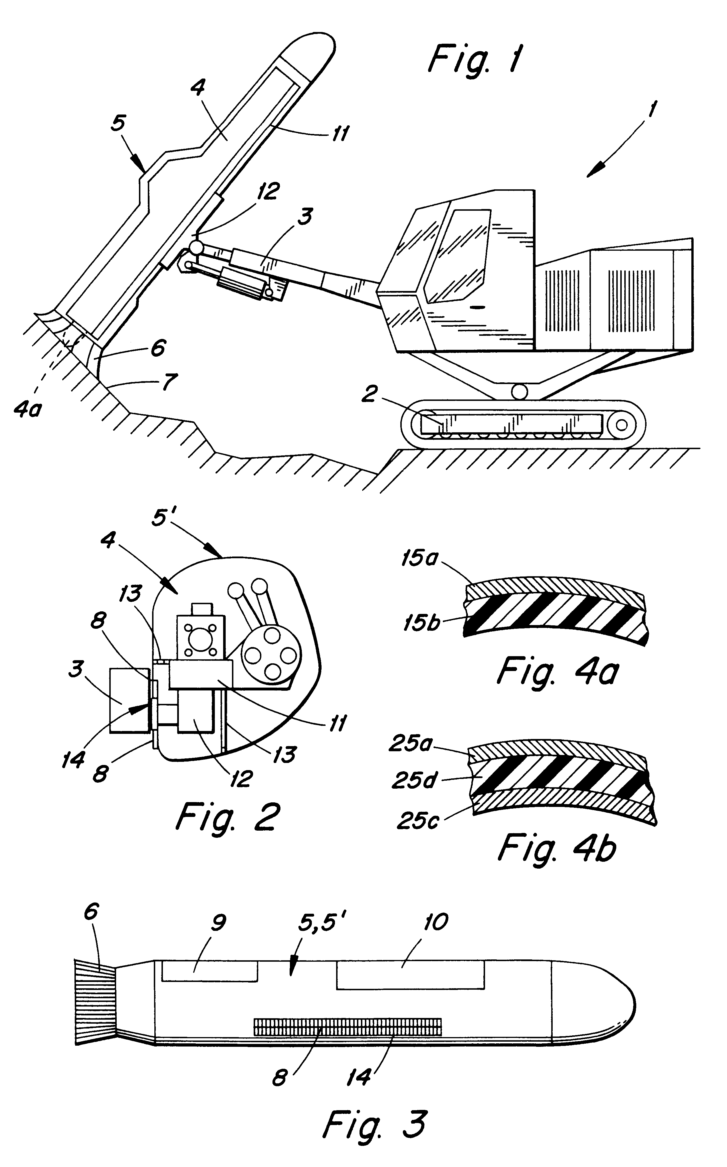
The basic idea behind the present invention is that around the drilling equipment mounted to the free end of the rock drilling rig's boom there is provided a casing structure that prevents the noise generated during drilling from spreading to the surroundings of the drilling site. The casing is arranged to cover both the drilling equipment and the feed beam substantially completely. The lower end of the casing is provided with an opening that allows the drill rod to be extended therethrough. Essential in the present invention is also that the fastening of the casing is arranged so that the casing is mounted and supported to the feed beam, and the feed beam is movable in relation to the cradle attached to the free end of the boom. An essential point is also that the casing is intended to be mounted so that there is free space between the casing and the drilling equipment as well as between the casing and the feed beam, whereby the vibrations and noise generated during drilling cannot be so easily transferred to the casing. The basic idea of a first aspect of the present invention is that also the cradle is enclosed by the casing. The basic idea of a second aspect of the present invention is that the opening that enables the movement between the casing and the cradle, or between the casing and the boom end, is provided with a noise curtain that seals the opening but allows casing movements. Further, the basic idea of a third aspect of the present invention is that the noise curtain is made of flexible bristles or strips. The basic idea of a fourth aspect of the present invention is that the casing is, at desired points, provided with hatches that can be opened and closed by remote control for observing and controlling drilling or the operation of the drilling equipment. Further, the basic idea of a fifth aspect of the present invention is that the casing comprises two nested shells with insulating material between them. Still further, the basic idea of a sixth aspect of the present invention is that the lower and of the casing, i.e. the end that faces the surface to be drilled, is provided with a flexible section that during drilling seals the gap between the lower end of the casing and the surface to be drilled.
The advantage of encapsulating is that the noise generated during rock drilling can be conveniently insulated and abated, whereby the noise no longer causes problems in the surroundings. This makes it possible to carry out drilling operations more freely even in residential areas, not restricted by the time of day or day of the week. Therefore, the degree of utilization of drilling equipment can be raised and work projects completed in less time. Noise protection pursuant to the present invention also improves working conditions, as unpleasant noise no longer exists. Noise attenuation also increases safety at work, as those working in the area are better able to hear the various warning signals and approaching vehicles. A further advantage of encapsulating is that it not only offers protection against noise but also serves as mechanical protection for the drilling equipment. The casing provides protection against dirt and dust both during operation and while in storage, which diminishes faults occurring in the equipment. The casing makes it easier to keep the drilling equipment clean while the casing itself is simple to keep clean. In addition, maintenance and repairs are easier to carry out as the drilling equipment inside the casing is cleaner. Encapsulation also protects the drilling equipment against other external influences, such as humidity and vandalism. A further advantage of the casing is that it protects the surroundings and prevents severe hazard situations in the event of sudden drilling equipment failure whereby broken fragments would fly to the surroundings. The casing also protects against persons getting caught in the moving parts of the drilling equipment. All in all, encapsulating offers significant advantages in improving safety at work. A further advantage provided by the casing is that as it forms the visible part of the equipment attached to the boom end, it can be used for improving the general appearance of the rig. The casing need not necessarily be made of any particularly strong material as it is not subjected to considerable forces. The casing does not have any role in the mounting and supporting of the drilling equipment, it merely forms a sound-proof shell around the drilling equipment. Therefore, the casing is easy to install and remove. A further advantage is that as the casing is connected to the drilling equipment only through vibration-dampened rubber bushings or equivalent dampeners, no frame noise and vibrations are transferred to the casing. A solution pursuant to the invention, with the feed beam also encapsulated, provides far better noise attenuation than solutions where noise can freely spread to the surroundings via the feed beam.

Problems solved by technology

This causes problems especially when drilling is carried out near residential or business buildings.
In such areas, the working hours are limited to certain times of the day, which, of course, considerably slows down the progress of work.
Drilling noise also causes inconvenience to those working at the site.
In addition, there are other persons moving or working at the site, and they may become subjected to the noise.
The problem with this solution is, however, that the drilling equipment and the feed beam are connected to the boom through the flexible support elements only.
This structure does not provide the required accuracy for the drilling; nor does it provide other necessary support for drilling.
A casing construction of the described type is also expensive to build, and maintenance of drilling equipment becomes difficult.
As most of the feed beam is left outside the casing, the problem is that drilling noise is able to escape to the surroundings through the uncovered section of the feed beam.

Method used


Image

  • Casing for noise attenuation in a rock drilling rig
  • Casing for noise attenuation in a rock drilling rig

Examples


Embodiment Construction

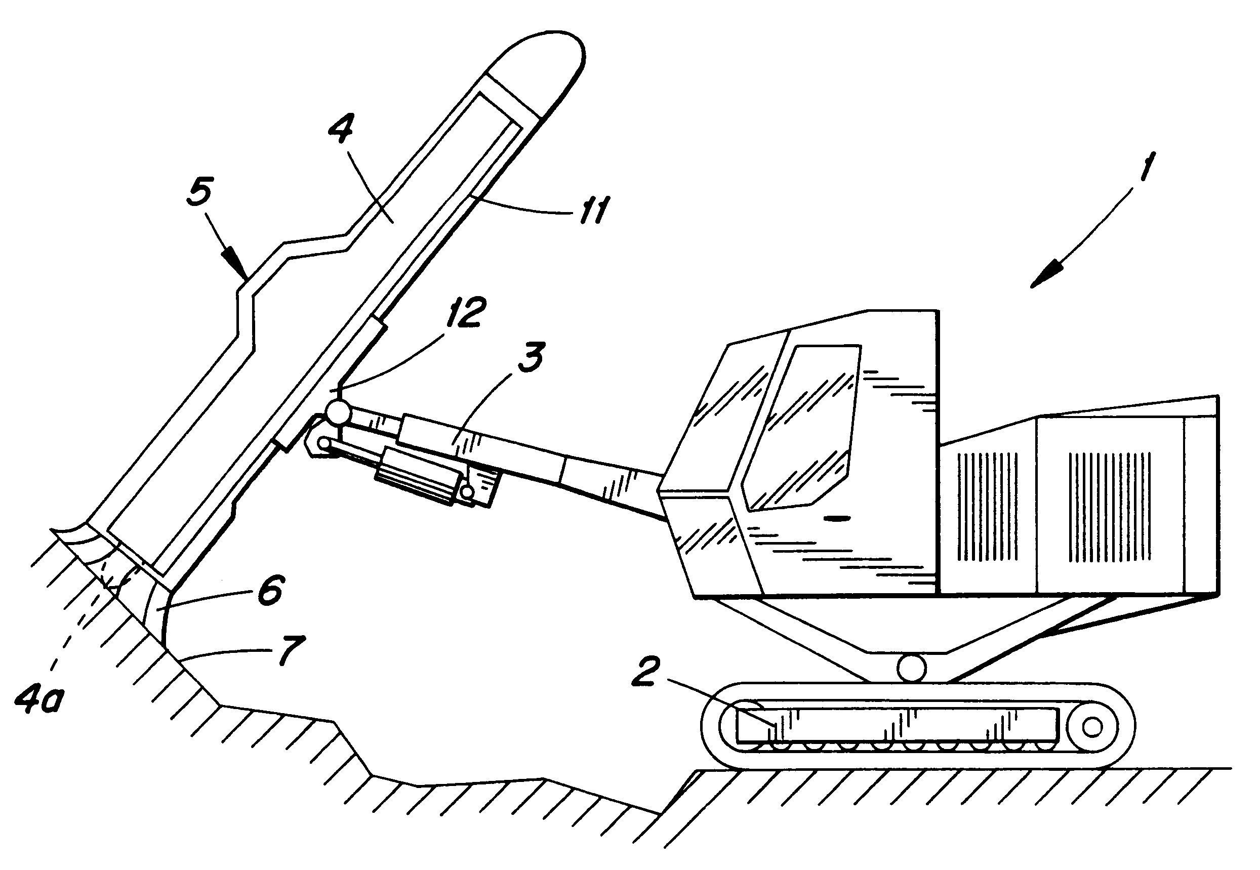
FIG. 1 is a schematic view of a rock drilling rig equipped with a casing according to the present invention. The drilling rig 1 comprises a movable carrier 2, a boom 3 attached to the carrier and movable in a variety of directions as is conventional. Drilling mechanism or equipment 4 having auxiliary devices is mounted to the free end of the boom 3. The drilling mechanism includes a front drilling head 4a for contacting the rock being drilled. In addition to the normal drilling equipment, i.e. a rock drill and rod handler, the drilling equipment may also include various rock bolting and charging devices, as well as the equipment for indexing them. The drilling equipment is mounted to a feed beam 11, in relation to which the rock drill can be moved. The feed beam is carried by a cradle 12 mounted to the end of the boom and is movable relative to the cradle. For the sake of clarity, the drilling equipment, the feed beam, and the cradle are only schematically shown in the drawings. The...


PUM


Abstract

A rock drilling rig includes a movable carrier with a boom attached to it and movable in various ways. The free end of the boom is provided with drilling equipment. The drilling equipment is enclosed in a casing that prevents noise generated during drilling from spreading to the surroundings. The casing is arranged to move together with a feed beam and relative to the cradle mounted on the end of the boom. A flexible noise attenuating skirt projects forwardly from a front end of the casing for forming a sealed chamber around a drilling head.

Description

The invention relates to a rock drilling rig and especially to a noise abatement structure therefor.PRIOR ARTTypically, a rock drilling rig for drilling into rock comprises a movable carrier equipped with a boom that is movable in various ways. The free end of the boom has the equipment necessary for actual drilling, including a rock drill as well as accessories and auxiliary equipment used for drilling into rock. The boom may be carrying, for instance, rock bolting devices for reinforcing rock, and charging equipment. Known solutions also include a cradle at the end of the boom, and a feed beam carrying the drilling equipment can be moved in relation to the cradle in -its longitudinal direction using suitable transferring mechanisms.Most currently used solutions have no noise attenuation whatsoever for the rock drilling equipment, and the noise generated during drilling is free to spread to the surroundings of the drilling site. This causes problems especially when drilling is carr...

Claims


Application Information

Patent Timeline
IPC IPC(8): E21B41/00E21B7/02E21B12/00E21B15/00E21B19/08
CPCE21B7/025E21B21/015Y10S173/02
Inventor VENTO, ARTOTANTARI, JUKKASAARINEN, KARIJULKUNEN, PASILINTU, VEIKKOPELTOLA, SEPPOSORMUNEN, TAPANI
Owner SANDVIK INTELLECTUAL PROPERTY AB
Learn More