Machine tool with tool changer

Inactive Publication Date: 2001-03-13
CHUGAI PHARMA CO LTD +2
View PDF9 Cites 11 Cited by
  • Summary
  • Abstract
  • Description
  • Claims
  • Application Information

AI Technical Summary

Benefits of technology

One object of the invention is to so improve a machine tool of the type initially mentione

Problems solved by technology

A further point is that the known design with rods is unsuitable for accurate work.
The disadvantage here is that on the one hand owing to such guide rails the tool magazine arranged behind is difficult to access and on the other hand owing to special design considerations it

Method used


Image

  • Machine tool with tool changer
  • Machine tool with tool changer
  • Machine tool with tool changer

Examples


Embodiment Construction

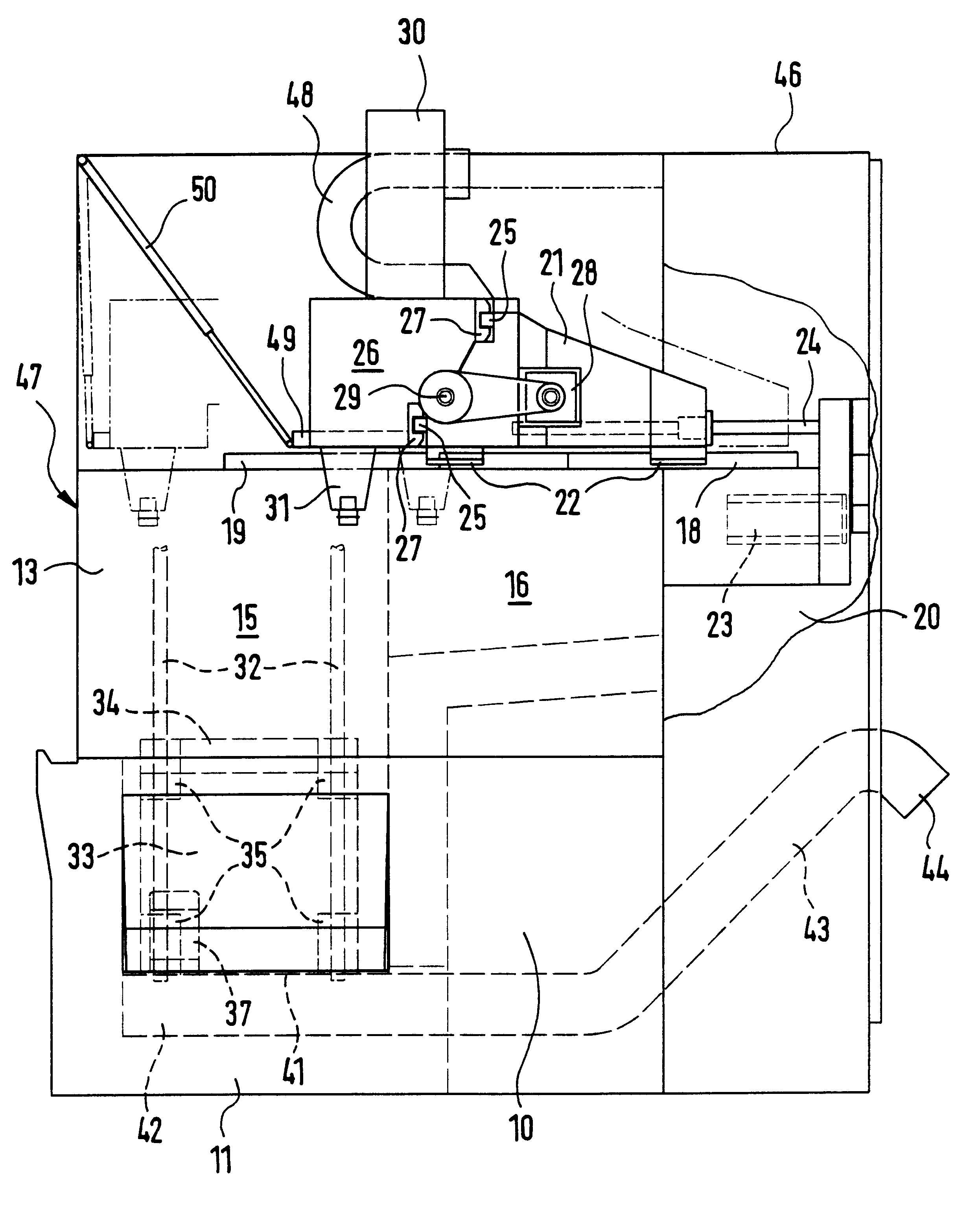
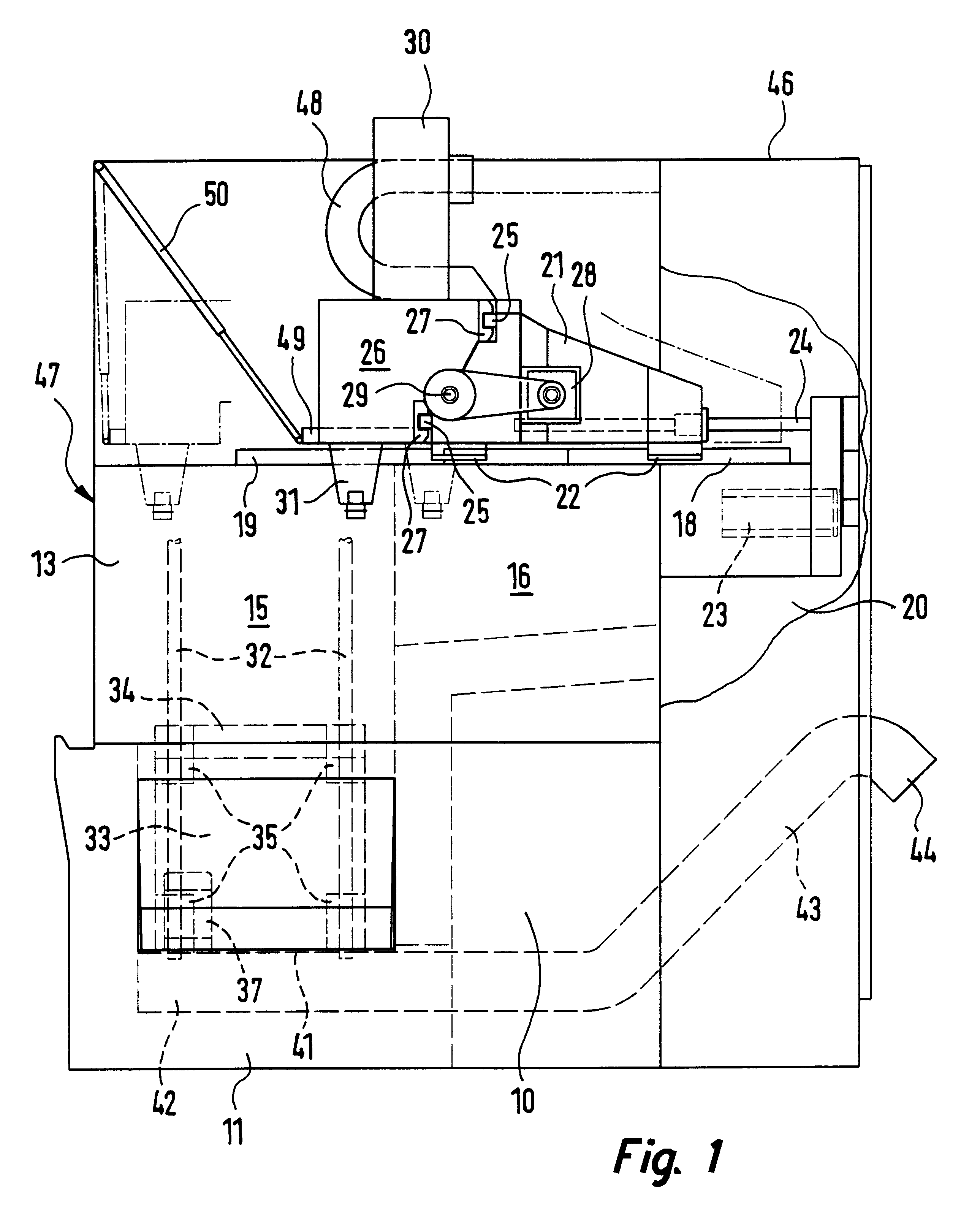
The machine tool illustrated in FIGS. 1 to 4 may be designed in the form of a drilling machine, a grinding machine, a milling machine or a combined machining center.

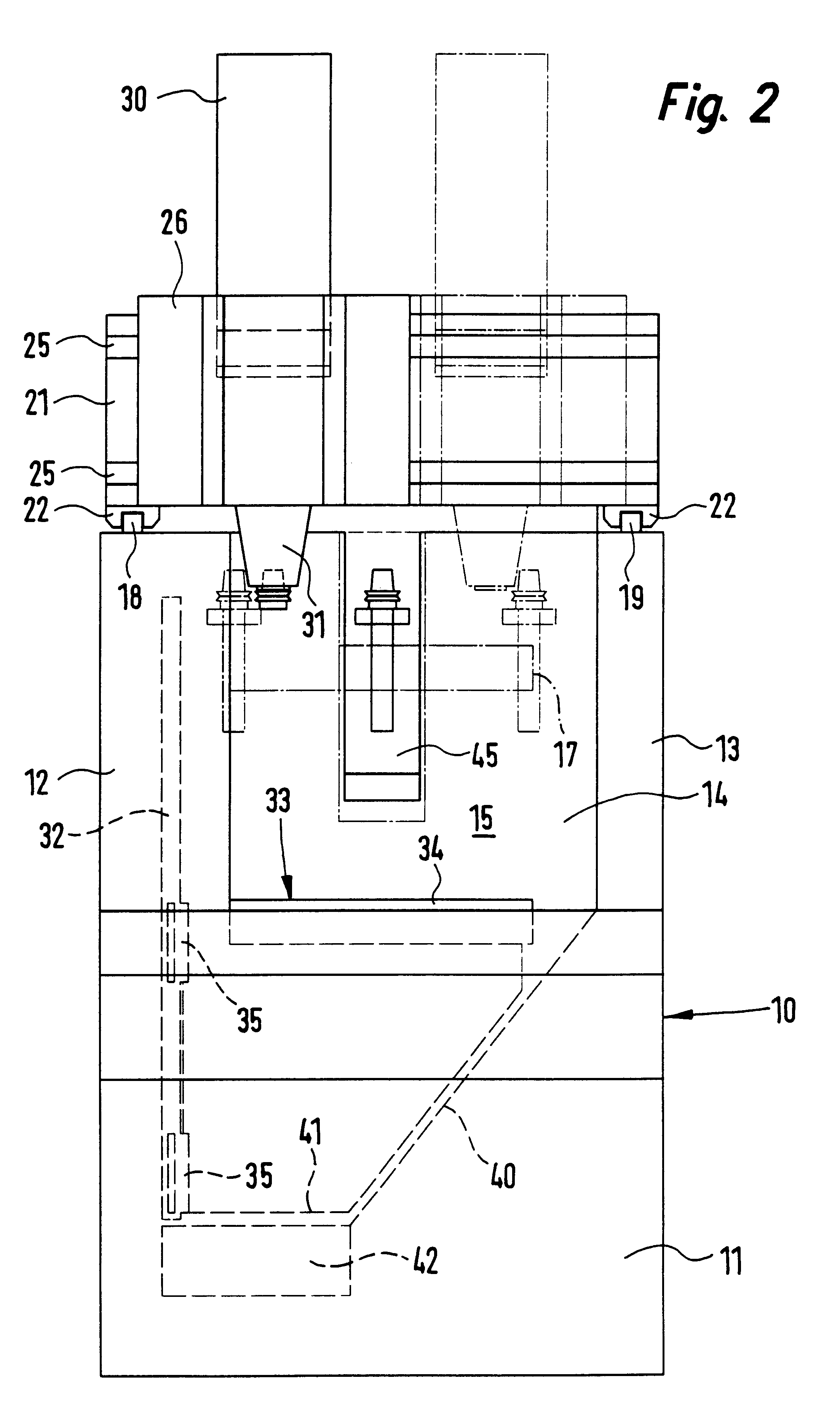
A machine stand 10 constituting the bed of the machine possesses a bottom basis area 11, from which on two opposite sides two side walls 12 and 13 extend upward. Together with a transverse wall 14 connecting them these side walls 12 and 13 delimit a working area 15 of the machine. A stand area 16 connecting these two side walls 12 and 13 on the side, remote from the machining area 15, comprises a tool magazine 17, designed in the form of a revolver magazine and arranged centrally in this stand area 16, that is to say substantially in the middle between the two side walls 12 and 13.

On the two side walls 12 and 13 two parallel guide rails 18 and 19 are secured in the longitudinal direction of these side walls 12 and 13 in the longitudinal direction of the machine stand 10. The guide rail 18 is substantially longer than the...


PUM

PropertyMeasurementUnit
Shapeaaaaaaaaaa
Areaaaaaaaaaaa

Abstract

A machine tool and more particularly a drilling and/or milling machine, which has a machine stand, on which a slide arrangement, which runs on guide rails and is motor driven, is able to be moved in either direction of horizontal motion. On this slide arrangement a working head is arranged to receive rotary tools. Underneath the working head in a working area a power driven machining table runs along vertical guide rails for the performance of vertical working movements. The working area is laterally delimited by two side walls at least partly, such side walls extending in parallelism to the longitudinal direction, the vertical guide rails for the working table being arranged on one of the side walls. This means that there is a simple design allowing for removal of shavings to the rear and accordingly a narrow form of the machine. A further point is that a transverse wall connecting the side walls remains free so that there is simple access to a tool magazine arranged behind these part

Description

The invention relates to a machine tool and more especially a drilling and / or milling machine, comprising a machine stand, on which a first slide, which is borne on guide rails and is power driven, is able to be moved in a first horizontal direction of motion, a second slide, which is power driven, adapted to run in a second horizontal direction of motion perpendicular to the first direction of motion on the first slide, a working head, arranged on the second slide and having a drive device for at least one rotary tool, and a machining table in a working area underneath the working head, said head being adapted to be power-moved on vertical guide rails for the performance of vertical machining movements during the machining of workpieces by the working head.THE PRIOR ARTSuch a machine tool as disclosed in the German patent publication 1,477,580 A comprises a machine stand, which is made up of two plates joined together by the intermediary of four vertical rods. In this arrangement t...

Claims


Application Information

Patent Timeline
IPC IPC(8): B23Q11/00B23Q1/62B23Q1/00B23Q1/01B23Q1/25B23Q3/157
CPCB23Q1/015B23Q1/017B23Q1/623B23Q11/0053Y10T409/308288Y10T483/1793Y10T409/307728Y10T483/115Y10T409/30392Y10T408/91Y10T483/179Y10T29/50
Inventor BRAUN, HANS-DIETER
Owner CHUGAI PHARMA CO LTD
Why Eureka
Try Eureka