Process for fabricating an optical mirror array

a mirror array and optical technology, applied in the field of optical mirror array fabrication, can solve the problems of affecting the optical mirror array,

Inactive Publication Date: 2001-03-13
LUCENT TECH INC
View PDF9 Cites 135 Cited by
  • Summary
  • Abstract
  • Description
  • Claims
  • Application Information

AI Technical Summary

Problems solved by technology

Spacing the mirrors as close as possible is problematic because each mirror typically requires a support structure.
The electrical interconnection density can also present a serious bottleneck.
As the number of mirrors in a tilting array increases, the number of electrical lead lines also increases, and these lead lines must be crowded into confined spaces.
Hence there is a limit as to how small the leads can be made and how closely they can be spaced apart from each other.
The routing of this n

Method used


Image

  • Process for fabricating an optical mirror array
  • Process for fabricating an optical mirror array
  • Process for fabricating an optical mirror array

Examples


Embodiment Construction

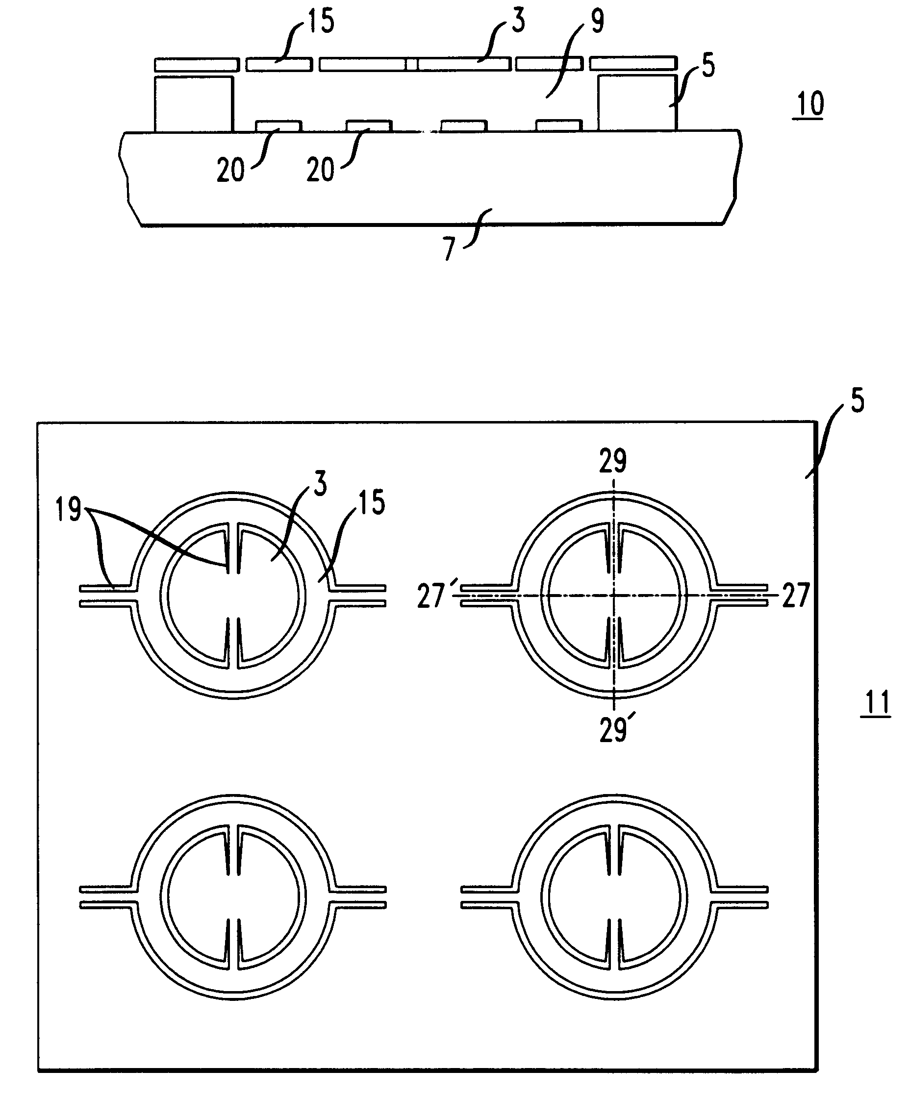
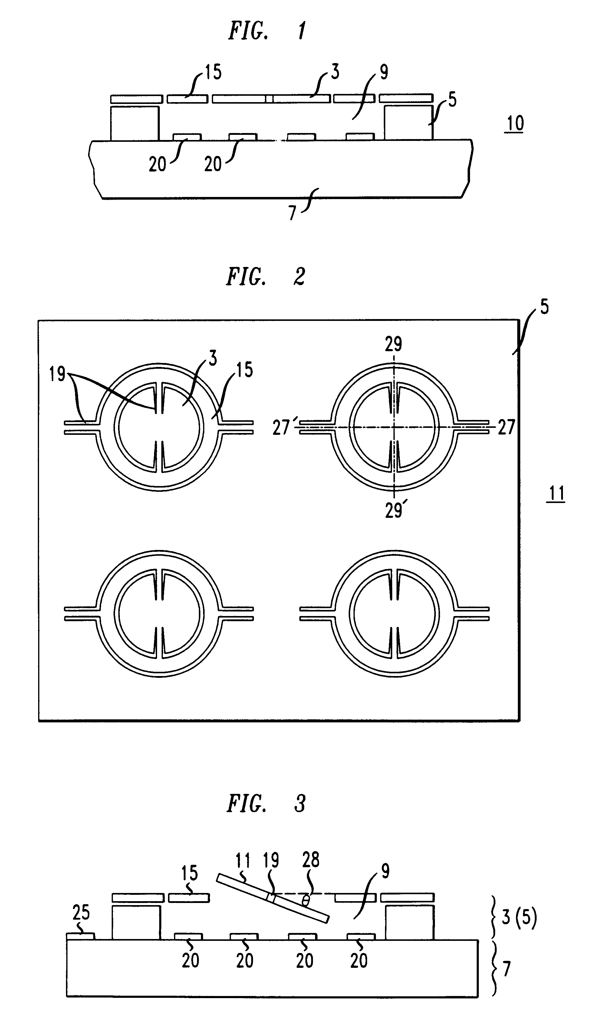
An electro-optic device having the structure depicted in FIG. 2 was modeled. The array of cavities were assumed to be circular, with center-to-center spacings of about 1.0 mm. Based on the center-to center cavity spacings of about 1.0 mm, each mirror of the array had a diameter of about 650 .mu.m. The outer diameter of the support structure (gimbal) was about 815 .mu.m.

Assuming that each mirror had a thickness of about 2 .mu.m, the torsional members coupling the mirror to the supporting structure had lengths of about 175 .mu.m, and the torsional members coupling the supporting structure to the substrate had lengths of about 295 .mu.m. Based on the dimensions of the mirrors and supporting structure the gap spacing between the mirror and the bottom of the cavity was assumed to be about 165 .mu.m.

Semicircular electrodes each having a radius of about 175 .mu.m were positioned in the cavities below the mirror.

Calculations determined that a potential of about 200 volts applied between one...


PUM


Abstract

An electro-optic device which includes a mirror array attached to a base substrate is disclosed. The mirror array comprises a substrate having a plurality of spaced-apart mirrors with underlying cavities (each having a diameter at least about the same size as that of the overlying mirror) formed therein. The base substrate includes a plurality of electrodes as well as a plurality of electrical interconnections. The mirror array is attached to the base substrate so that each mirror of the array as well as a cavity are supported above a set of electrodes. Each mirror of the mirror array rotates relative to the major plane of the substrate in response to an electrical signal. The application of an electrical potential to each mirror relative to at least one electrode of the set of electrodes causes the desired rotation (depending on the magnitude of the electrical potential) up to an angle of about 20 degrees.

Description

The present invention relates generally to optical communication systems and more particularly to an optical device having a mirror array.DESCRIPTION OF THE RELATED ARTElectro-optic devices often employ an array of micro-machined mirrors, each mirror being individually movable in response to an electrical signal. For example, the mirrors can each be cantilevered and moved by an electrostatic force. Typically, electro-optic mirror array devices can be used as, for example, optical cross connects in optical communication systems, visual presentations and displays. Generally, each mirror of the cross-connect is addressed by a number of electrical lead lines and receives a beam of light from, for example, an individual optical fiber in a fiber optic bundle. The beams of light reflected from the mirrors are individually directed to a prespecified location (for example, another fiber optic bundle) by individually moving the mirrors.It is desirable to have a high density of optical transfe...

Claims


Application Information

Patent Timeline
IPC IPC(8): G02B26/08
CPCG02B26/0841Y10S359/904
Inventor GREYWALL, DENNIS STANLEY
Owner LUCENT TECH INC
Why Eureka
Try Eureka