RMS-to-DC converter with balanced multi-tanh triplet squaring cells

a triplet squaring cell, balanced technology, applied in the field of rmstodc converters, can solve the problems of not being able to detect true rms detectors, not operating well at microwave frequencies, and reducing the sensitive to low signal levels

Inactive Publication Date: 2001-03-20
ANALOG DEVICES INC
View PDF8 Cites 71 Cited by
  • Summary
  • Abstract
  • Description
  • Claims
  • Application Information

AI Technical Summary

Problems solved by technology

However, like the other computing converters, it utilizes nonlinear signal processing elements.
Although the techniques discussed above can provide an accurate measure of the true RMS value of a signal at relatively low frequencies, they do not operate well at microwave frequencies, i.e., upwards of 1 GHz.
Signal measuring devices capable of operation at microwave frequencies are available, e.g., diode detectors, but they are not t

Method used


Image

  • RMS-to-DC converter with balanced multi-tanh triplet squaring cells
  • RMS-to-DC converter with balanced multi-tanh triplet squaring cells
  • RMS-to-DC converter with balanced multi-tanh triplet squaring cells

Examples


Embodiment Construction

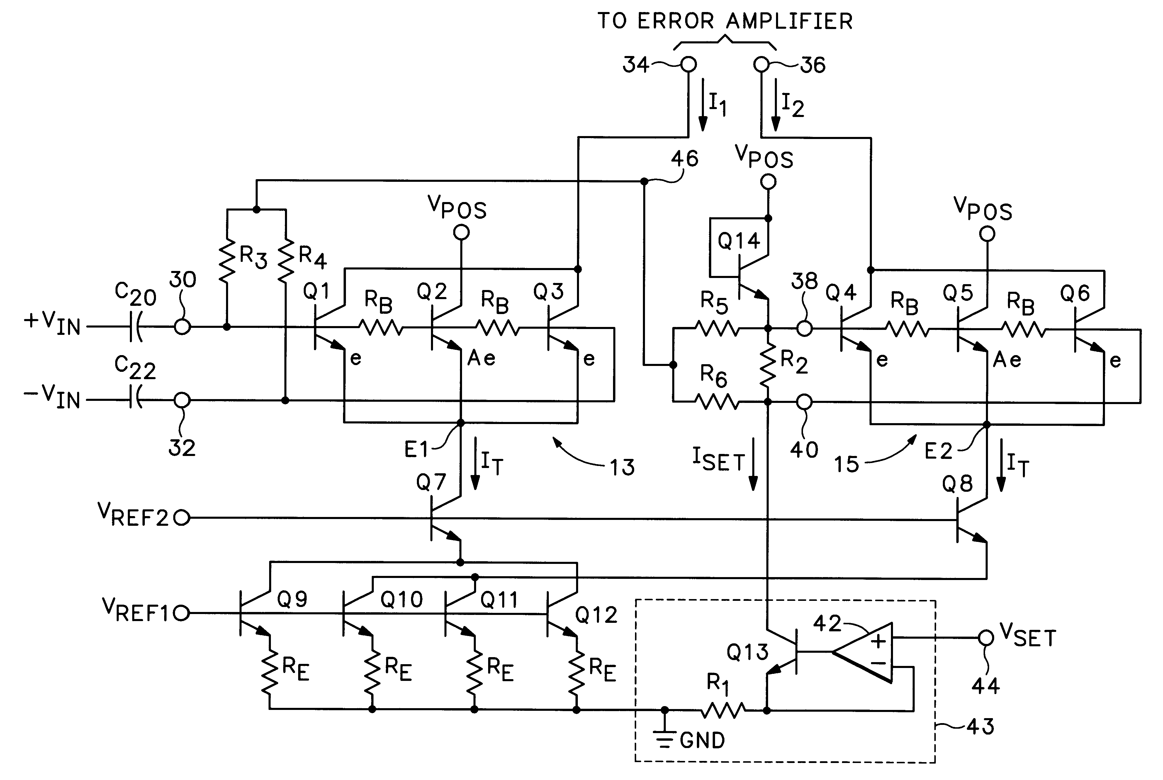
FIGS. 10-13 together form a schematic diagram of a preferred embodiment of an RMS-to-DC converter in accordance with the present invention. This embodiment is intended for implementation as a monolithic integrated circuit.

Referring to FIG. 10, the HF squaring cell 13 and current source transistors Q9-Q12 are arranged in essentially the same configuration as in FIG. 6, but the cascode transistor Q7 is eliminated, and instead, the common emitter node E1 is connected directly to the collectors of Q9 and Q12. The collectors of Q10 and Q11 are connected together at node E2. An RC filter includes a capacitor C4 connected between a node EMHF and GND and a resistor R7 connected between the nodes E1 and EMHF.

Referring to FIG. 11, the DC squaring cell 15 has the same structure as in FIG. 6, but cascode transistor Q8 is eliminated, and the common emitter node E2 is connected directly to the collectors of Q10 and Q11 in FIG. 10. A balancing circuit, which is essentially an operational amplifier...


PUM


Abstract

An RMS-to-DC converter implements the difference-of-squares function by utilizing two identical squaring cells operating in opposition to generate two signals. An error amplifier nulls the difference between the signals. When used in a measurement mode, one of the squaring cells receives the signal to be measured, and the output of the error amplifier, which provides a measure of the RMS value of the input signal, is connected to the input of the second squaring cell, thereby closing the feedback loop around the second squaring cell. When used in a control mode, a set-point signal is applied to the second squaring cell, and the output of the error amplifier is used to control a variable-gain device such as a power amplifier which provides the input to the first squaring cell, thereby closing the feedback loop around the first squaring cell. Accurate square law approximation at microwave frequencies can be achieved by implementing the squaring cells as series-connected three-transistor multi-tanh transconductance cells. By using carefully balanced squaring cells and a well-balanced error amplifier, approximation errors are cancelled and accurate RMS measurement is realized at high frequencies. A feedforward bootstrapping feature uses an op amp to balance the voltages at the common nodes of the transconductance squaring cells and also provides a balanced differential input drive to one of the squaring cells. A base current compensation circuit for providing accurate base compensation current to both of the squaring cells prevents errors due to DC offset voltages.

Description

1. Field of the InventionThe present invention relates generally to RMS-to-DC converters, and more particularly, to an RMS-to-DC converter that utilizes balanced squaring cells and is capable of measuring true power at microwave frequencies.2. Description of the Related ArtRMS-to-DC converters are used to convert the RMS (root-mean-square) value of an arbitrary signal into a quasi-DC signal that represents the true power level of the signal. Numerous techniques have been devised for performing RMS-to-DC conversions. One of the most fundamental is known as the "thermal" method. With the thermal method, the signal is used to generate heat in a resistive dissipator. The heat is then measured, usually by establishing a temperature balance using a second dissipator. The DC input to the second dissipator then provides a measure of the RMS value of the signal. Another technique involves "computing" converters which utilize nonlinear analog signal processing. Examples of computing converter...

Claims


Application Information

Patent Timeline
IPC IPC(8): G01R19/02G06G7/00G06G7/20
CPCG01R19/02G06G7/20
Inventor GILBERT, BARRIE
Owner ANALOG DEVICES INC
Why Eureka
Try Eureka