Main memory control apparatus for use in a memory having non-cacheable address space allocated to DMA accesses

a control apparatus and memory technology, applied in the direction of memory adressing/allocation/relocation, data conversion, instruments, etc., can solve the problems of invalid data in the cache memory, long access time, and inability to snoop on the cost reduction function of many cache memory users, so as to maintain data consistency

Inactive Publication Date: 2001-03-20
HITACHI LTD
View PDF9 Cites 21 Cited by
  • Summary
  • Abstract
  • Description
  • Claims
  • Application Information

AI Technical Summary

Benefits of technology

An object of the present invention is to overcome the above-mentioned disadvantages in the prior art, and to realize a main memory control apparatus for controlling access to a main memory unit from a CPU having no snooping function and a DMA enable device, so that data access can be made to the main memory unit at a high speed while maintaining consistency of data between the cache memory and the main memory unit.
With the arrangement set forth above, the data in the main memory means to which write access is made from the access enable device is always present in the second address area and will never exist in the cache memory. Therefore, consistency of data between the cache memory and the main memory means can be maintained and a need of invalidating the data in the cache memory at the time the access enable device writes data is eliminated. Also, the read buffer memory can be accessed at a higher speed than the main memory means. Accordingly, even a CPU having no snooping function that monitors access to the main memory means from other device than the CPU, i.e., the access enable device, can maintain consistency of data between the cache memory and the main memory means and shorten a data access time.

Problems solved by technology

Accordingly, those CPU's incorporate cache memories for improvement of performance, but many of them have no snooping function for cost reduction.
But if data in a main storage area which is accessed by the DMA enable devices exits in the cache memory at the DMA start-up, the data in the cache memory is invalidated.
However, the above method (1) is disadvantageous in that since CPU access to all the area of the main memory unit or the area thereof which is accessed by DMA enable devices is made directly to the main memory unit, an access time is longer than that required to make access to the cache memory.
Also, in the above method (2), it is probable that each time write access to the main memory unit is made at the DMA start-up, the contents of the cache memory are invalidated.
This results is disadvantages of reducing utilization of the cache memory, lowering a cache hit ratio, and prolonging an average access time of the CPU to the main memory unit.

Method used


Image

  • Main memory control apparatus for use in a memory having non-cacheable address space allocated to DMA accesses
  • Main memory control apparatus for use in a memory having non-cacheable address space allocated to DMA accesses
  • Main memory control apparatus for use in a memory having non-cacheable address space allocated to DMA accesses

Examples


Embodiment Construction

An embodiment of the present invention will be described hereunder with reference to the accompanying drawings.

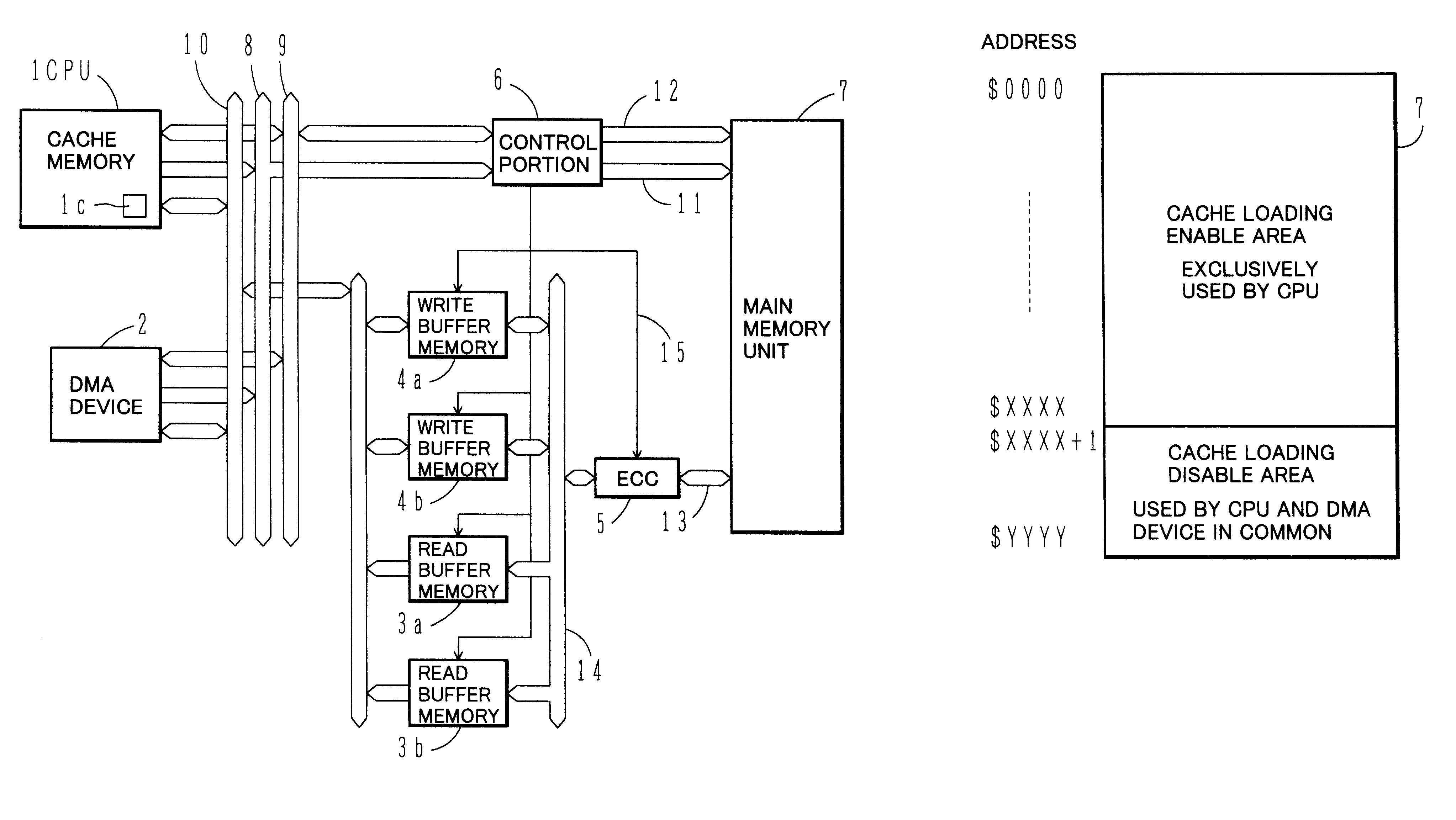
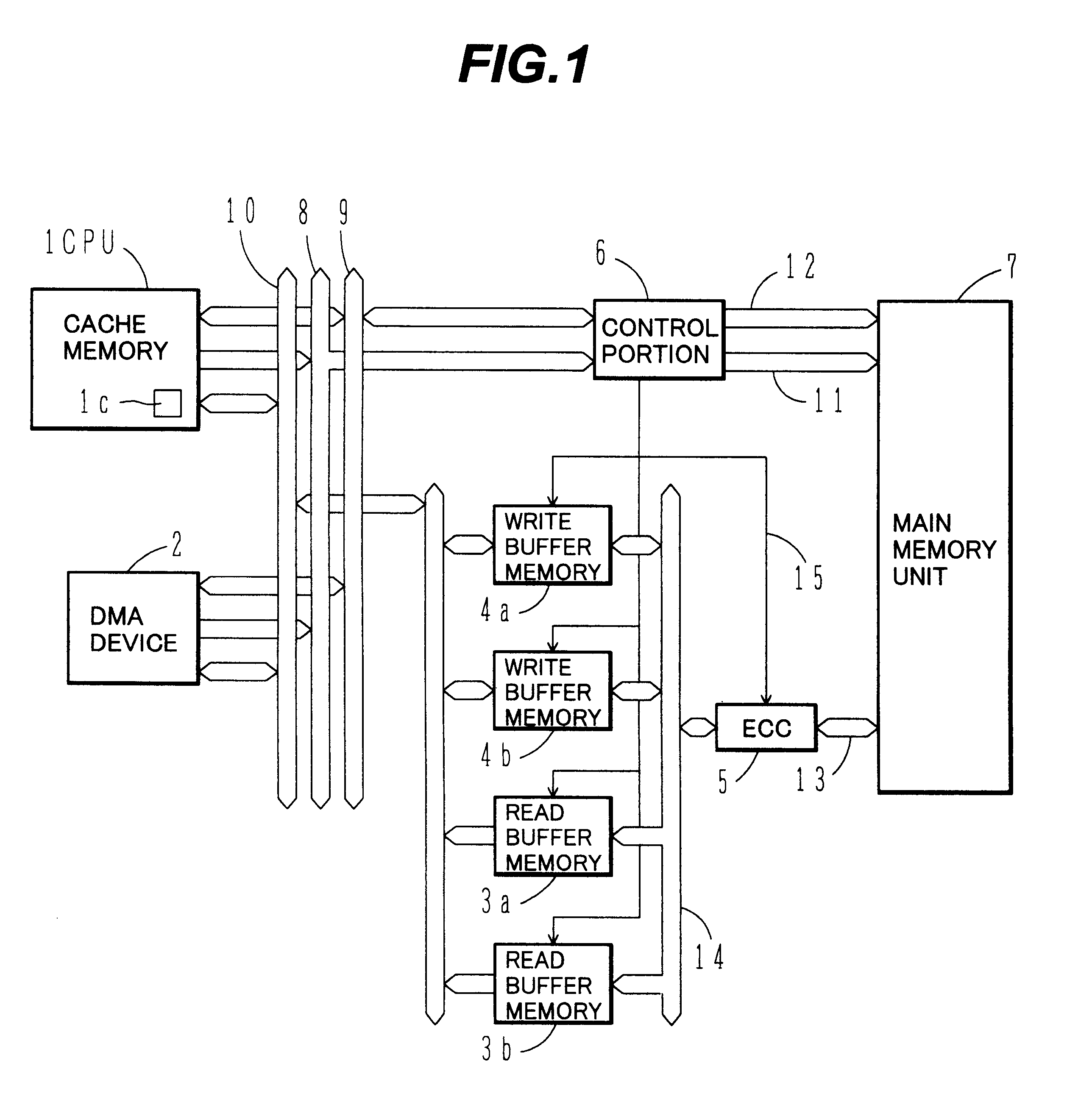
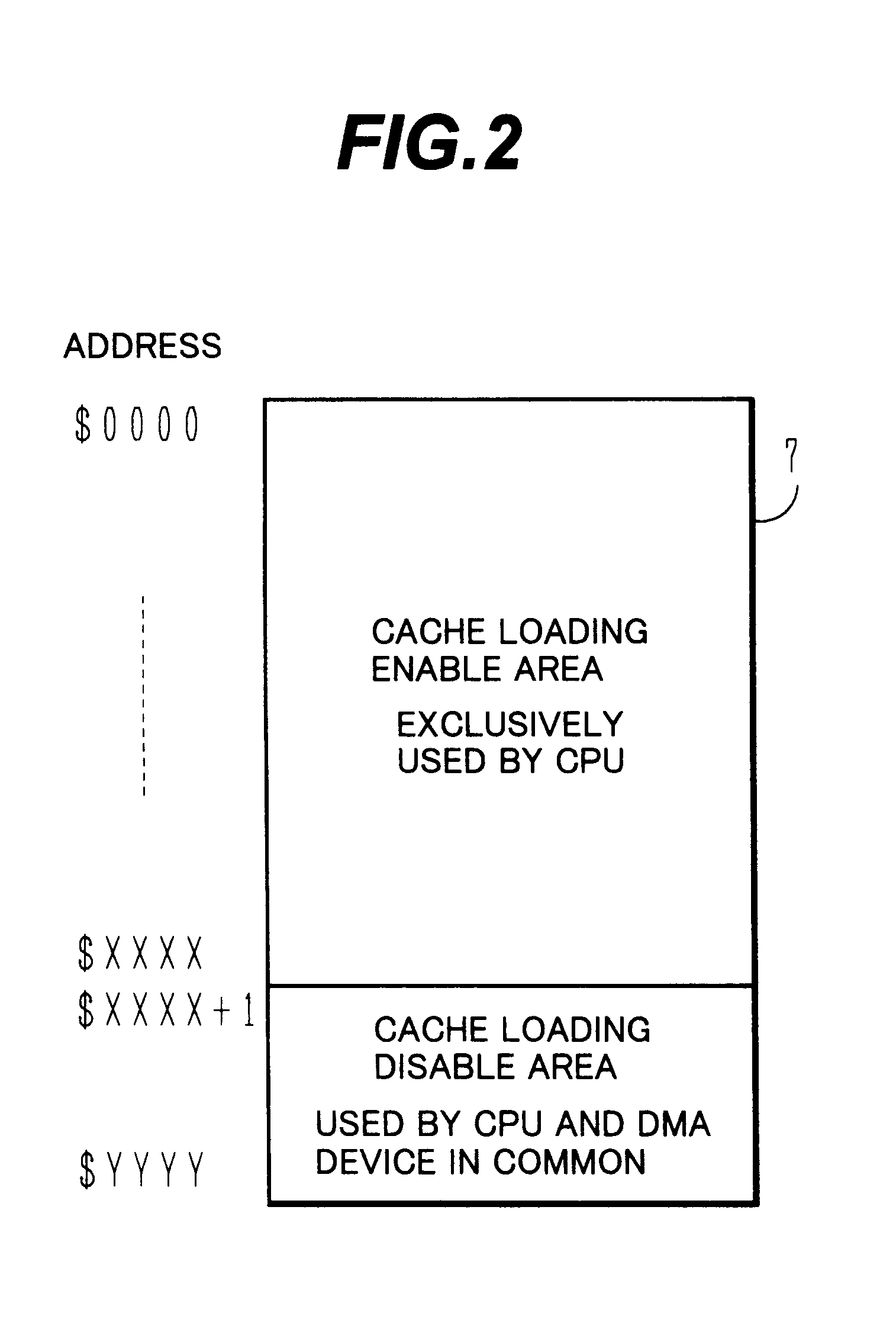
FIG. 1 is a general block diagram of a main memory control apparatus for use in a computer system according to one embodiment of the present invention. In FIG. 1, denoted by reference numeral 1 is a CPU which incorporates a cache memory 1c, but has not a snooping function. Numeral 2 denotes a DMA enable device (access enable device). Numeral 7 denotes a main memory unit (storage). Of an address area of the main memory unit 7, an address area from which data cannot be loaded into the cache memory 1c in the CPU 1 is used by the CPU 1 and the DMA device 2 in common. The remaining address area of the main memory unit 7 is allocated as an address area from which data can be loaded into the cache memory 1c in the CPU 1.

Denoted by 3a, 3b are read buffer memories and 4a, 4b are write buffer memories. Each of these buffer memories has a capacity capable of storing a certain quantity...


PUM


Abstract

A CPU and a DMA device employ in common an address area from which data cannot be loaded into a cache memory. A read buffer memory and a write buffer memory loading therein data read from and written into that address area are provided. In read access from the CPU or DMA device to the common address area, if data to be accessed exists in any buffer memory, the data in the buffer memory is transferred to the CPU or DMA device. If data to be accessed does not exist in any buffer memory, data at addresses different from the read access address from the CPU or DMA device only in lower bits of fixed length is read from the main memory unit and then loaded into the buffer memory after performing data error checking and correcting of the read data.

Description

BACKGROUND OF THE INVENTION1. Field of the InventionThe present invention relates to a main memory control apparatus capable of realizing high-speed access to a main memory unit in a computer system.2. Description of the Related ArtSome CPU's include cache memories storing part of the contents stored in a main memory unit, aiming at high-speed access to the main memory unit. In such a CPU, consistency or sameness of data between the cache memory and the main memory unit is maintained by a snooping function that monitors access to the main memory unit from DMA (Direct Memory Access) enable devices other than the CPU.Some of CPU's including cache memories, however, have no snooping function. Particularly, built-in CPU's which are becoming commonly used in commercial applications incorporate cache memories for improvement of performance, but often have no snooping function for cost reduction. In those CPU's having no snooping function, consistency of stored data between a cache memory ...

Claims


Application Information

Patent Timeline
Patent Type & Authority Patents(United States)
IPC IPC(8): G06F12/08G06F12/16
CPCG06F12/0848G06F12/0888
Inventor SUGAYA, YUJI
Owner HITACHI LTD
Why Eureka
Try Eureka