Method for reception of multicarrier signals and related apparatus

a multi-carrier and receiver technology, applied in the field of multi-carrier receiver technology, can solve the problems of questionable practicability of such methods, and achieve the effect of increasing the reliability of results

Inactive Publication Date: 2001-03-27
DEUTSCHE THOMSON-BRANDT GMBH
View PDF9 Cites 47 Cited by
  • Summary
  • Abstract
  • Description
  • Claims
  • Application Information

AI Technical Summary

Benefits of technology

The main question is whether this is an agreeable basis and whether further exceptions can be avoided. New services may require additional frequency numbers and may not accept the rule of transmitting the frequency information for surrounding transmitters. On the other hand, a solution with several offsets for all frequencies increases the number of tuning positions by e.g. 100% per additional offset position. This would have a great impact on the receiver design and also on the tuning performance.
which makes about 140 ms for DAB Mode I and about 50 ms for DAB Mode II. To increase the reliability of the result, one more frame could be included, thereby increasing the values to 235 ms and 75 ms (Modes I and II, respectively; see table 38 and clause 15.1 of ETS 300 401).
However, the test on system signal (DAB) conformity must start with one mode, probably Mode I in Band III, and if the result for Mode I is negative (which is the general assumption for a next step to be carried out with the same procedure), then an additional Mode II check must be carried out. It can be assumed that the additional time is less than 50 ms. The general check time for a tuning point is estimated to be in the range of 160 ms to 250 ms whereby the latter value provides more reliability.
The invention allows to get a fast and reliable information on the status of the received signal, whether or not it is a system-conform signal with enough noise distance. This feature reduces the scanning time for a frequency range or a number of defined transmitter frequencies by a factor of 5 to 10.

Problems solved by technology

However, it is questionable whether such method is practicable.

Method used


Image

  • Method for reception of multicarrier signals and related apparatus
  • Method for reception of multicarrier signals and related apparatus
  • Method for reception of multicarrier signals and related apparatus

Examples


Embodiment Construction

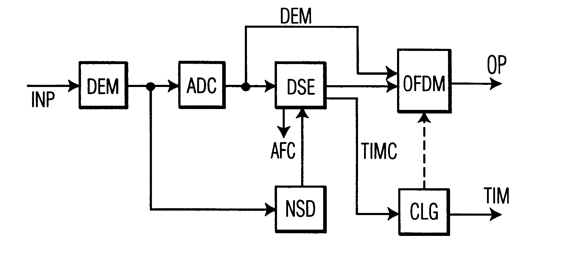
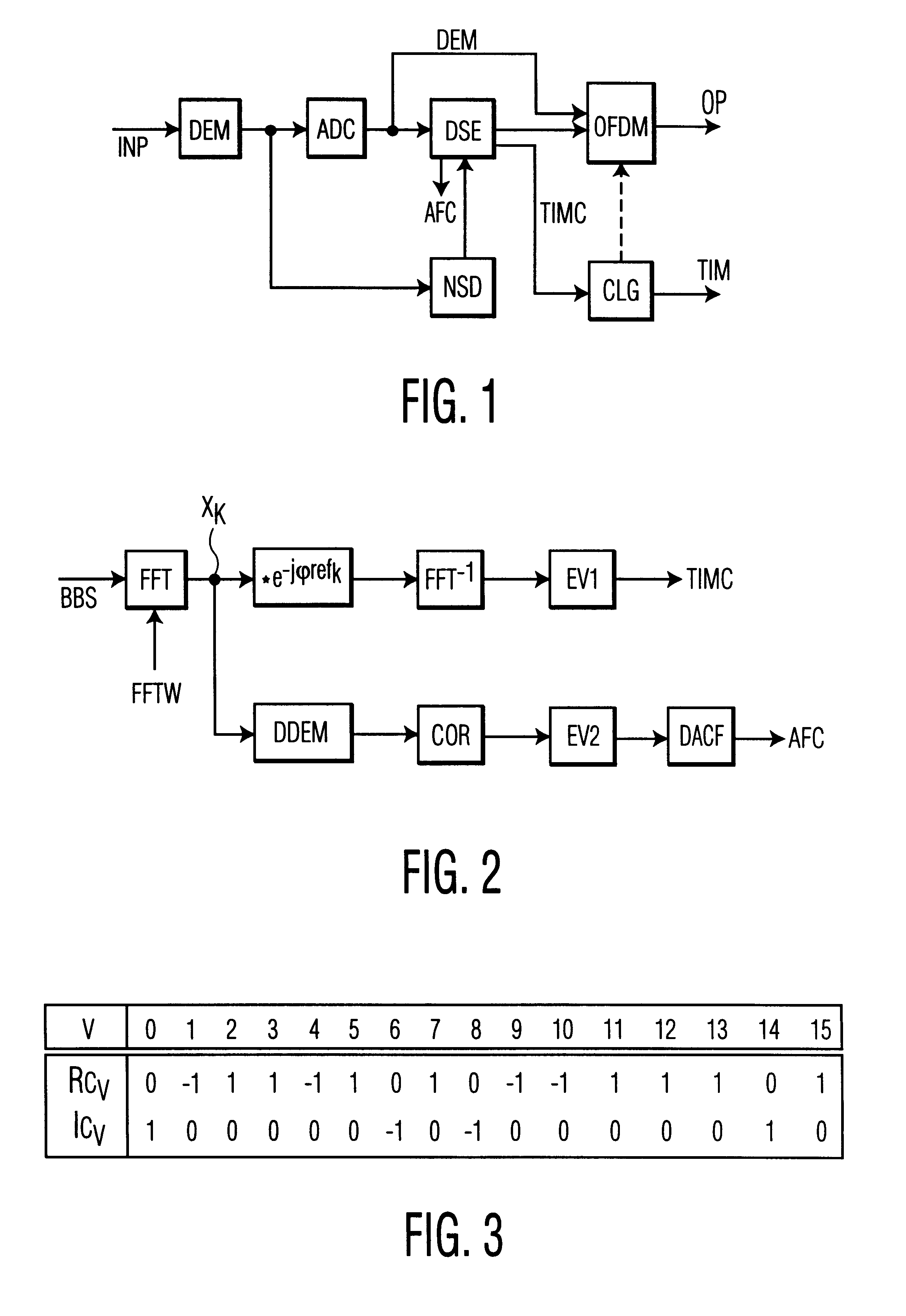
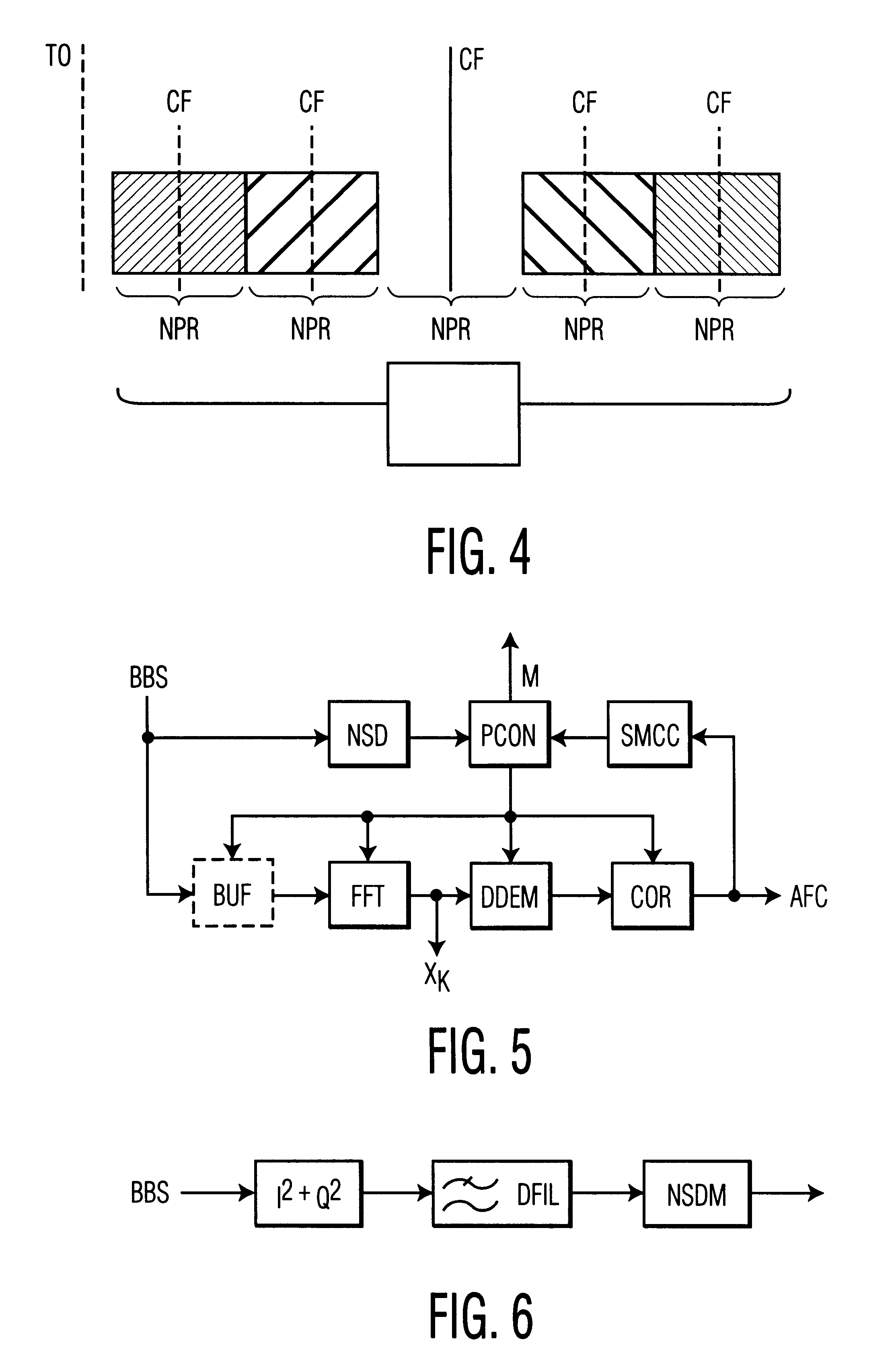
In FIG. 1 a received input signal INP is demodulated in a demodulator circuit DEM. Following A-to-D conversion, a respective time section of the received signal may be stored in the receiver. In a prior art receiver as well as in the inventive receiver time synchronisation starts with a detection of the null symbol in a succeeding null signal part detector NSD, which implies envelope calculation, matched filtering and center calculation. This can be done either by analogue / digital or by pure digital processing. The further processing in the inventive receiver is carried out as follows: If a system-conform signal is detected, the output signal of demodulator DEM is converted to a digital signal in analog to digital converter ADC and input as a baseband signal BBS to OFDM decoder OFDM which delivers the final output signal OP. The output signal of ADC also enters a digital synchronisation evaluator DSE which controls OFDM and which supplies control data TIMC to a clock generator CLG. ...


PUM


Abstract

A problem in the reception of terrestrially transmitted digital multicarrier broadcast signals is synchronization in case a receiver is switched on or tuned to another channel. The time required by the receiver to reach a given tuning frequency with adequate accuracy and to determine that the currently received signal is not a system-compliant signal is reduced significantly if a characteristic value calculated from correlation values between a windowed and FFT transformed section of the received signal and a reference symbol stored in the receiver does not exceed a pre-defined threshold. In such case the receiver can go ahead to the next tuning frequency. If, however, the characteristic value exceeds that threshold, then a system-compliant signal is found, even with an offset. The multicarrier signal will be further decoded in the normal way. Such conformity check can also be carried out in the subsequent normal reception mode.

Description

The present invention relates to the reception of multicarrier RF signals and to a corresponding apparatus.Various methods for terrestrial transmission of digital broadcast signals are known, having modulation types like OFDM, QPSK and QAM. A main concern in connection with such systems is to find a system-conform signal in case a receiver is switched on or tuned to another channel. Examples for such broadcast signals are DVB (digital video broadcast), HDTV-T (hierarchical digital television transmission) and DAB (digital audio broadcast) signals.Considerations on DAB receiver tuning concepts are so far based on the assumption that an acceptable number of fixed DAB center frequencies can be used, if necessary with small offsets of quite below the 16 kHz step size. A reasonable approach is given by the CEPT (conference Europeenne des administrations des postes et des telecommunications) T-DAB allotment plan of July 1995. This approach would result in a reasonable time to scan the ent...

Claims


Application Information

Patent Timeline
Patent Type & Authority Patents(United States)
IPC IPC(8): H04L27/26H04L5/02H04H20/00
CPCH04L5/023H04L27/2647
Inventor KLANK, OTTOLAABS, JUERGENKLAUSBERGER, WOLFGANG
Owner DEUTSCHE THOMSON-BRANDT GMBH
Why Eureka
Try Eureka