
Method for monitoring plants with mechanical components

a technology of mechanical components and monitoring methods, applied in the field of mechanical monitoring methods, can solve the problems of affecting the operation of the plant, the temporal behavior of the measured values to be determined for monitoring is not fixed, and the plant cannot operate at a fixed operating or working point, etc., and it is difficult to judge on the basis of the temporal behavior of the measured values, if at all, whether the plant is operating correctly

Inactive Publication Date: 2001-03-27
SULZER INNOTEC
View PDF17 Cites 83 Cited by
  • Summary
  • Abstract
  • Description
  • Claims
  • Application Information

AI Technical Summary

Benefits of technology

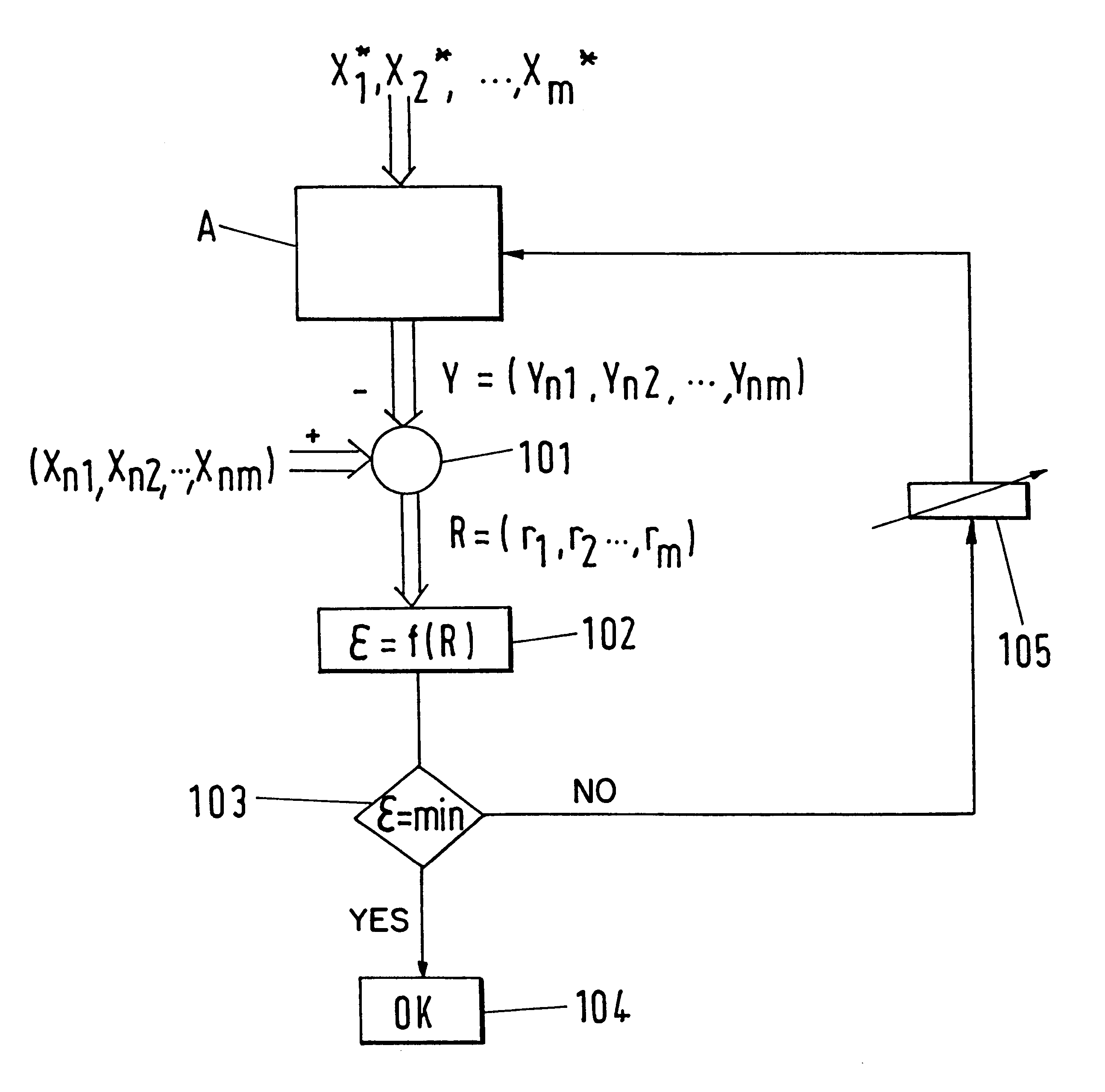
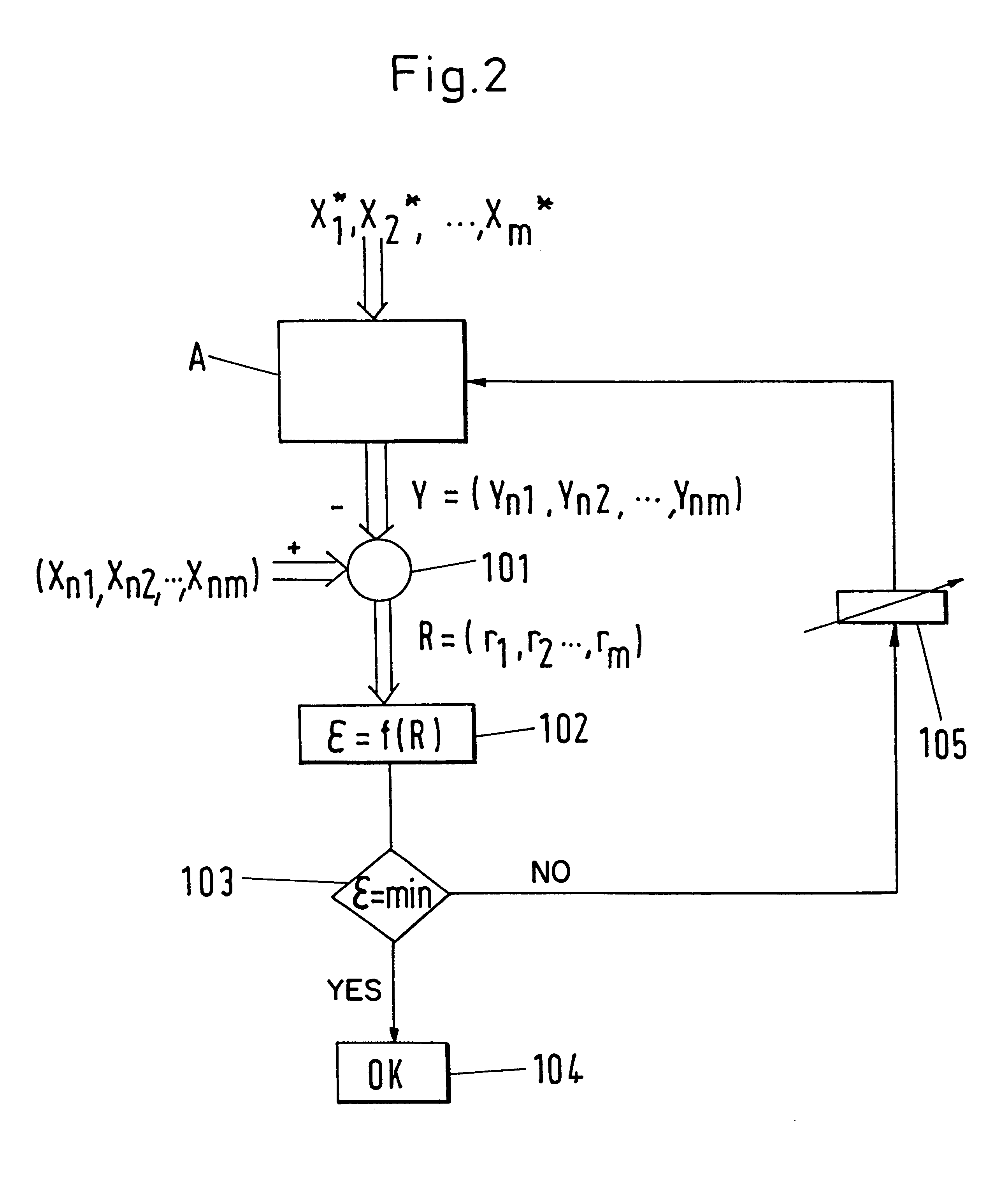
The method in accordance with the invention makes use of a monitoring variable which is independent of the respective current operating point, which means that fluctuations in the measured values for the parameters which are based merely on changes in the operating point do not lead to significant changes in the monitoring variable. The method thus takes into account the mutual influence between the parameters at varying working points. In other words, this means that the monitoring method in accordance with the invention does not operate with fixed threshold values for definite parameters, but rather that the threshold values are adapted to the respective current operating state. This permits a very reliable and early detection both of operating disturbances and of slowly progressing changes such as are caused, for example, by wear. The triggering of false alarms and the "overlooking" of operating disturbances, e.g. in operation at partial load, practically no longer arises in the method in accordance with the invention. This is advantageous, in particular, from the point of view of economy and safety. Through the reliable monitoring, unnecessary standstill times of the plant can be avoided and the maintenance costs significantly reduced.
It is also preferred to take the older models into account, in particular in a weighted manner, during the updating for the determination of the current model. The temporal behavior, for example, of an arising disturbance or a wear, can thereby be better estimated.

Problems solved by technology

Usually, however, components such as turbines do not operate at a fixed operating or working point, so that the temporal behavior of the measured values to be determined for monitoring exhibits pronounced fluctuations even in normal, that is, disturbance-free operation.
Therefore, it is very difficult to judge on the basis of the temporal behavior of the measured values--if at all--whether the plant is operating correctly, free of disturbance.
In addition, it is difficult to detect and to judge very slow temporal variations such as arise, for example, through operational wear.
In practice, however, this way is frequently too cost-intensive and laborious so that it is poorly suited for industrial applications in particular.
One reason for this is that industrial plants have an enormous complexity with numerous components in mutual interaction so that a moderately reliable physical model must take a large number of relationships between the individual parameters into account, through which its generation becomes an extremely difficult, time consuming and cost-intensive task.
This kind of monitoring has disadvantages however.
There is namely the danger that operational disturbances or faults actually existent in the plant are overlooked or detected too late.
On the other hand, it is possible for false alarms to be triggered, for example, when the turbine briefly operates at a very high load, so that the threshold value required for triggering the alarm is exceeded with out a defect being present.
A false alarm of this kind can lead to the plant being switched off without it actually being necessary, which is very disadvantageous, in particular, from the economic point of view.

Method used


Image

  • Method for monitoring plants with mechanical components
  • Method for monitoring plants with mechanical components
  • Method for monitoring plants with mechanical components

Examples


Embodiment Construction

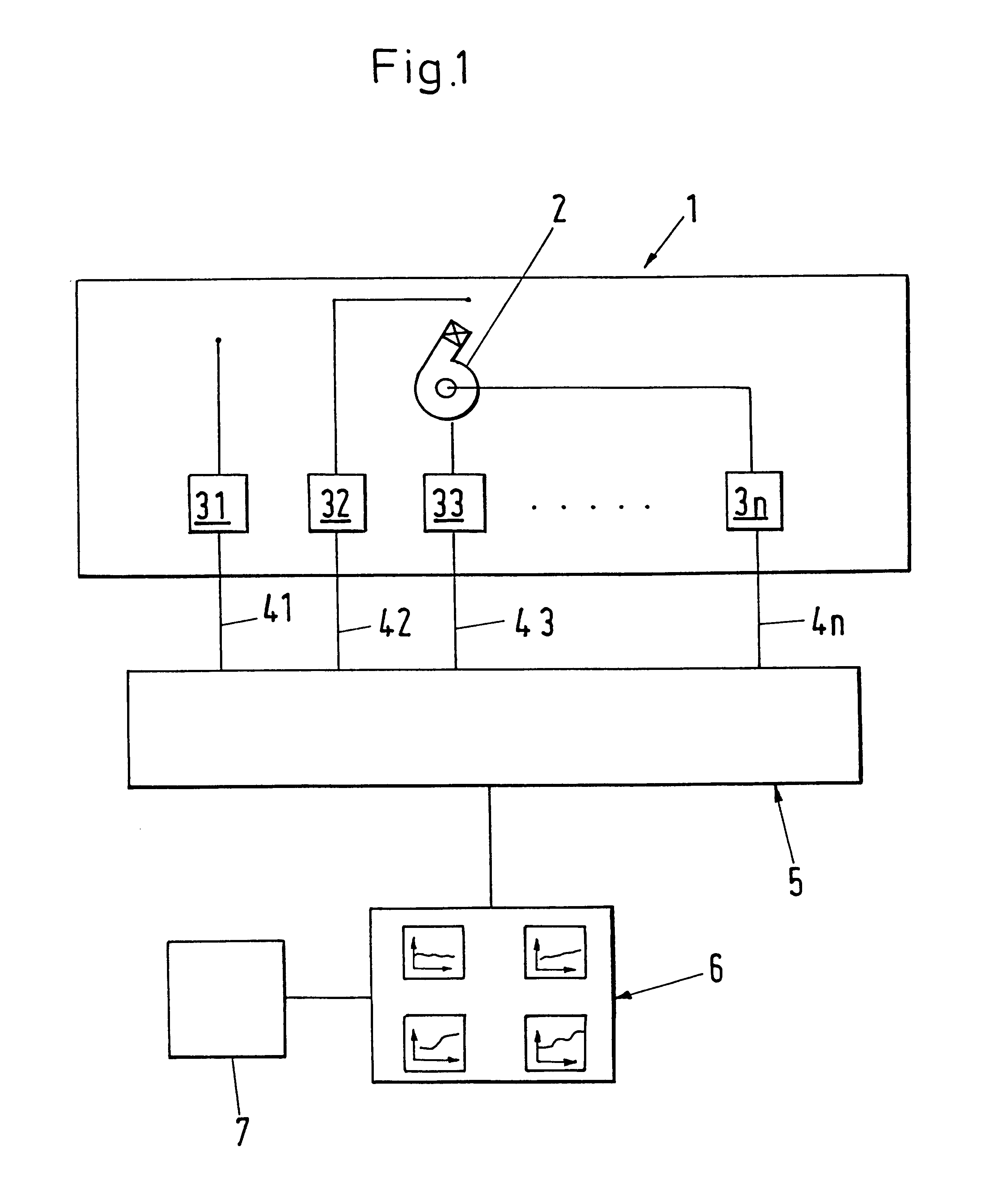
The method in accordance with the invention is explained in the following with exemplary character with reference to a hydroelectric power plant with turbines. In this, the hydroelectric power plant acts as a representative example of a plant to be monitored and the turbines serve as an example for the hydromechanical components of the plant. It is evident that the invention is not restricted to cases of this kind. The components can also be other flow machines such as, for example, pumps or other mechanical systems such as steam turbines, steam boilers, compressors, generators, motors, transmissions. The plants in which components of this kind are integrated can, for example, also be heating plants, locomotives, weaving machines or plasma spray plants.

The term "parameters" is understood to mean those directly or indirectly measurable variables which are useful for the characterization of the operating state of the components of the plant or which have an influence on the operating ...


PUM


Abstract

In a method for monitoring plants with mechanical components, measured values (xiT; xiu) are determined at predeterminable time intervals for a fixed set of parameters (xi). The measured values (xiT) which are determined for various working points during a modelling phase are used for the generation of a model for the operating behavior of the components. With the help of the model for the operating behavior at least one monitoring value (r; snu) is derived at predeterminable time intervals which is independent of the respective current working point. The temporal behavior of the monitoring value (r; snu) is used for estimating the wear in the components and / or for the detection of operating disturbances.

Description

1. Field of the InventionThe invention relates to a method for monitoring plants with mechanical, in particular hydromechanical, components.2. Description of the Prior ArtFor industrial applications, for example, for the generation of electrical energy, complex plants which comprise a large number of components are often used. As a representative example reference is made in the following to a hydroelectric power plant in which turbines are driven by means of hydraulic force for the generation of electrical energy. In this example, the hydromechanical components are thus the turbines, which are set rotating by flowing water and which drive the generators.From the points of view of safety and economy, it is very important to continuously monitor such plants and their components during operation in order to detect disturbances in the operation, that is, deviations from normal operating behavior, as early and reliably as possible. Often a plurality of parameters such as, for example, p...

Claims


Application Information

Patent Timeline
IPC IPC(8): G05B23/02G07C3/00
CPCG05B23/0254G07C3/00
Inventor MILEK, JANUSZGUETTINGER, HEINZ
Owner SULZER INNOTEC
Learn More