Vibration gyroscope

a gyroscope and vibration technology, applied in the direction of acceleration measurement using interia force, turn-sensitive devices, instruments, etc., can solve the problems of increasing manufacturing costs and difficulty in meeting the requirement of reducing equipment in size and thickness

Inactive Publication Date: 2001-04-03
MITSUI CHEM INC
View PDF15 Cites 29 Cited by
  • Summary
  • Abstract
  • Description
  • Claims
  • Application Information

AI Technical Summary

Benefits of technology

Another object of the present invention is to provide a vibratory gyroscope which can reduce its thickness and width.
As a result of a hard research, the present inventors have found that excellent characteristics are shown by a structure in which an angular velocity is obtained by providing a vibrator made of a piezoelectric substance with exciting electrodes to excite a vibration in a longitudinal direction by the exciting electrodes, and by detecting, by detective electrodes, a flexural vibration in a plane perpendicular to a rotation axis which is induced by Coriolis force generated by angular velocity around the rotation axis which is in a thickness wise direction of the vibrator.
According to the vibratory gyroscope of the above-described structure, an angular velocity sensor can be realized only by forming the exciting electrodes and the detective electrodes on the piezoelectric substance and the like, and it is possible to simplify the structure and to largely reduce the manufacturing cost as compared with the conventional vibratory gyroscope.
Further, since the gyroscope is constructed such that the thicknesswise direction of the vibrator is taken as the rotation axis and the flexural vibration in the plane perpendicular to the rotation axis is detected by the detective electrodes provided on the portion of the vibrator, the shape of the gyroscope is narrow in width and thin in thickness, and it is possible to make the sensor smaller as compared with the conventional vibratory gyroscope of three-dimensional structure.

Problems solved by technology

Since the conventional vibratory gyroscope has the structure in which the permanent elastic metal and the piezoelectric ceramic are stuck, there is a problem that the manufacturing cost is increased.
Further, since the conventional vibratory gyroscope has a shape which is longer in the rotation axis (Z axis) direction, when it is mounted in an electronic equipment, it is difficult to meet requirement for reducing the equipment in size and thickness.

Method used


Image

  • Vibration gyroscope
  • Vibration gyroscope
  • Vibration gyroscope

Examples


first embodiment

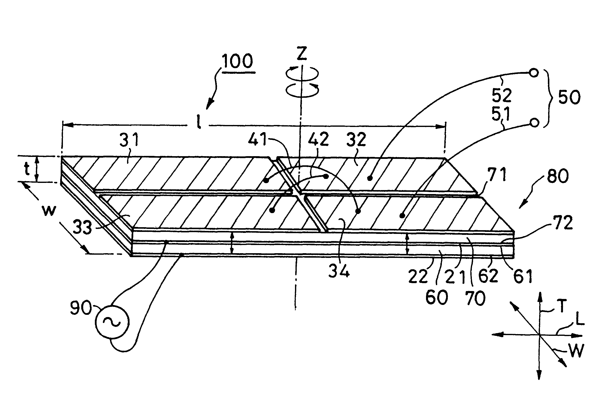
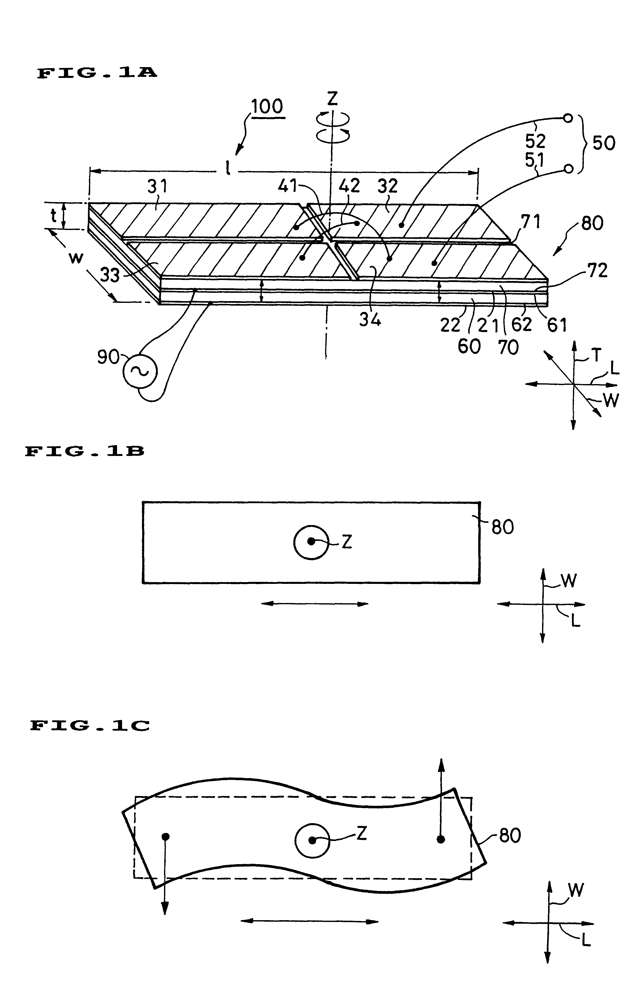
Referring to FIGS. 1A to 1C, a vibratory gyroscope 100 of a first embodiment includes a rectangular parallelepiped piezoelectric substance 80. The piezoelectric substance 80 is formed by laminating two piezoelectric substances 60 and 70 in a thicknesswise direction T.

An exciting electrode 22 is provided on the entire surface of a lower surface 62 of the lower piezoelectric substance 60. A grounding side exciting electrode 21 is provided on the entire surface of an upper surface 61 of the piezoelectric substance 60 and the entire surface of a lower surface 72 of the upper piezoelectric substance 70. The exciting electrodes 21 and 22 are connected to a driving signal source 90.

Detective electrodes 31 to 34 are provided on the upper surface 71 of the piezoelectric substance 70. The detective electrodes 31 to 34 are provided such as to substantially divide the upper surface 71 of the piezoelectric substance 70 into four. The detective electrodes 31 and 33 are provided symmetrically with...

second embodiment

Referring to FIG. 3, a vibratory gyroscope 100 of a second embodiment includes a rectangular parallelepiped piezoelectric substance 10. A grounding side exciting electrode 121 is provided on the entire surface of a lower surface 12 of the piezoelectric substance 10. An exciting electrode 122 is provided on a substantially left half region of an upper surface 11 of the piezoelectric substance 10. The exciting electrodes 121 and 122 are connected to a driving signal source 90.

Detective electrodes 131 and 132 are provided on a substantially right half region of the upper surface 11 of the piezoelectric substance 10. The detective electrodes 131 and 132 are provided such as to divide the substantially right half region of the piezoelectric substance 10 into two in the widthwise direction W. The detective electrodes 131 and 132 are provided symmetrically with respect to a plane which includes the rotation axis Z and which is in parallel to the longitudinal direction L and is perpendicula...

third embodiment

Referring to FIG. 4, a vibratory gyroscope 100 of a third embodiment includes a rectangular parallelepiped piezoelectric substance 10. A grounding side exciting electro de 221 is provided on the entire surface of a lower surface 12 of the piezoelectric substance 10. An exciting electrode 222 having a length of about one-third of the piezoelectric substance 10 in its longitudinal direction L is provided at the central portion of the upper surface 11 of the piezoelectric substance 10 in its longitudinal direction L such as to extend over substantially the entire width of the piezoelectric substance 10 in its widthwise direction W. The exciting electrodes 221 and 222 are connected to a driving signal source 90.

Detective electrodes 231 and 233 are provided on substantially left one-third region of the upper surface 11 of the piezoelectric substance 10 in the longitudinal direction L, and detective electrodes 232 and 234 are provided on substantially right one-third region of the upper s...


PUM


Abstract

A piezoelectric unit is composed of a plurality of piezoelectric elements. In one embodiment, a first driving electrode is provided over the whole surface of the lower surface of the piezoelectric element. A second driving electrode is provided over the whole surface between the piezoelectric elements. The driving electrodes are connected to a driving signal source. Detection electrodes are provided on the upper surface of the piezoelectric element. At least one of the detection electrodes is connected to one of the output terminals and at least another of the detection electrodes is connected to the other of the output electrodes. One piezoelectric element is polarized upward and another piezoelectric element is polarized downward. A vertical 1st order vibration is driven in a longitudinal direction and a 2nd order bending vibration is detected by the detection electrodes, and a voltage proportional to a coriolis force (rotational angular velocity) is outputted. With this construction, a vibration gyroscope having a reduced thickness and width can be produced.

Description

This application is the national phase under 35 U.S.C. .sctn.371 of prior PCT International Application No. PCT / JP97 / 03862 which has an International filing date of Oct. 24, 1997 which designated the United States of America, the entire contents of which are hereby incorporated by reference.1. Technical FieldThe present invention relates to a vibratory gyroscope, and more particularly, to a vibratory gyroscope used for navigation and the like of an automobile and the like.2. Background ArtFIG. 11 is a perspective view showing a structure of a conventional vibratory gyroscope. The above-mentioned vibratory gyroscope has a structure in which a exciting piezoelectric ceramic 3 and a detective piezoelectric ceramic 4 are stuck to a permanent elastic metal tuning fork type vibrator 1 having a square section. A principal axis direction of the permanent elastic metal tuning fork type vibrator 1 is taken as a Z axis, a normal direction of opposed one set of planes is taken as an X axis, and...

Claims


Application Information

Patent Timeline
Patent Type & Authority Patents(United States)
IPC IPC(8): G01C19/56G01C19/5656
CPCG01C19/5656
Inventor TOMIKAWA, YOSHIROKANAYAMA, KOUICHIKOISO, TAKESHI
Owner MITSUI CHEM INC
Why Eureka
Try Eureka