Filtration device for tank water for aquarium fish

a technology for aquarium fish and filtration device, which is applied in the direction of filtration separation, multi-stage water/sewage treatment, separation process, etc., can solve the problems of unfavorable fish removal, adverse effects on fish, and inability to perform removing and replacing specific filter media

Inactive Publication Date: 2001-04-03
TAKADA SHUNSUKE
View PDF24 Cites 35 Cited by
  • Summary
  • Abstract
  • Description
  • Claims
  • Application Information

AI Technical Summary

Problems solved by technology

There are several drawbacks to this type of filtration device.
In a larger device when the filter medium is not completely even in consistency water in the filtration device tends to follow its own narrow path instead of filtering throughout the medium, whereby causing an uneconomical and inefficiency condition called channeling.
Increasing the speed of water flow through the system can make a smaller sized filtration devi...

Method used


Image

  • Filtration device for tank water for aquarium fish
  • Filtration device for tank water for aquarium fish
  • Filtration device for tank water for aquarium fish

Examples


application example 1

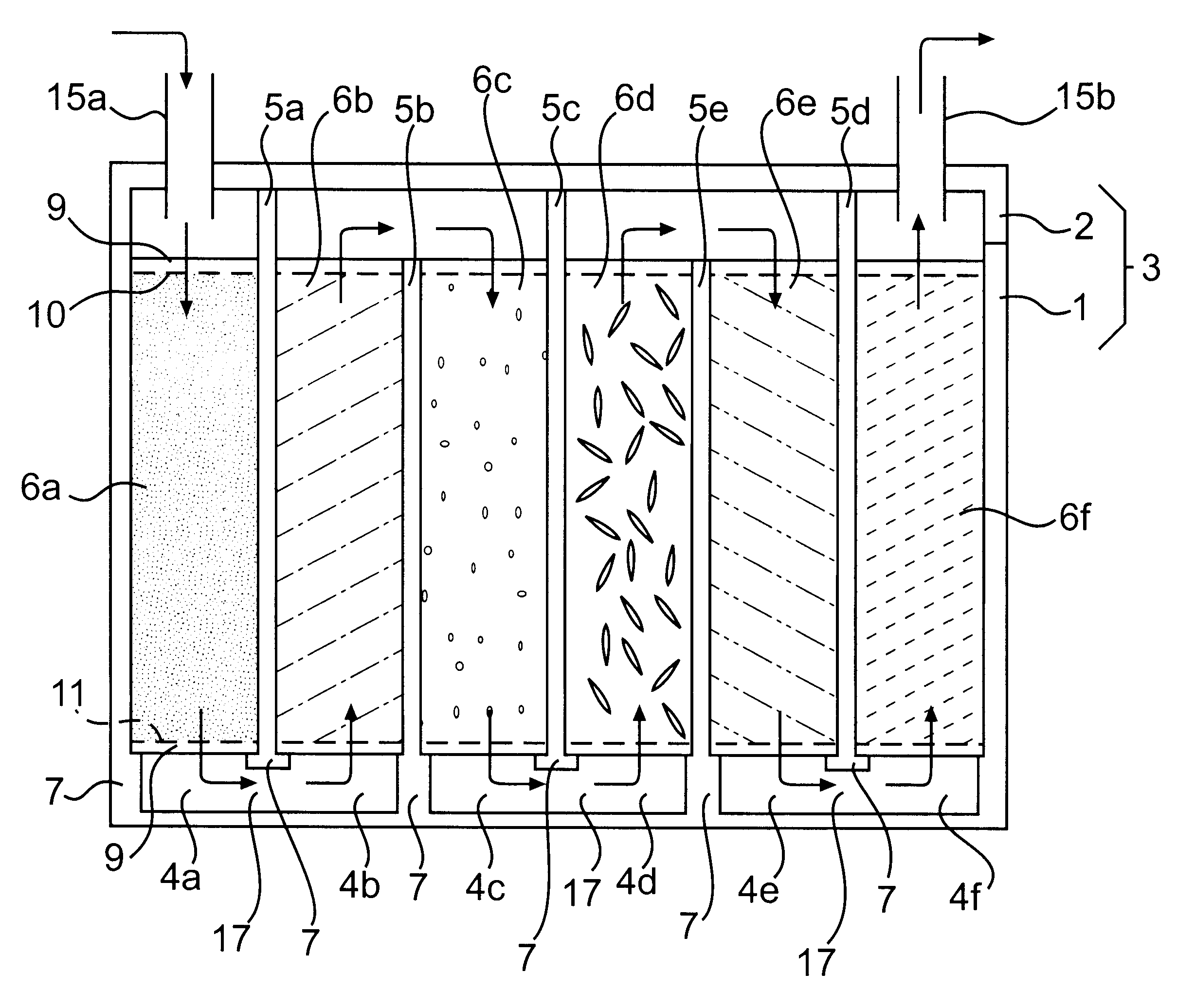
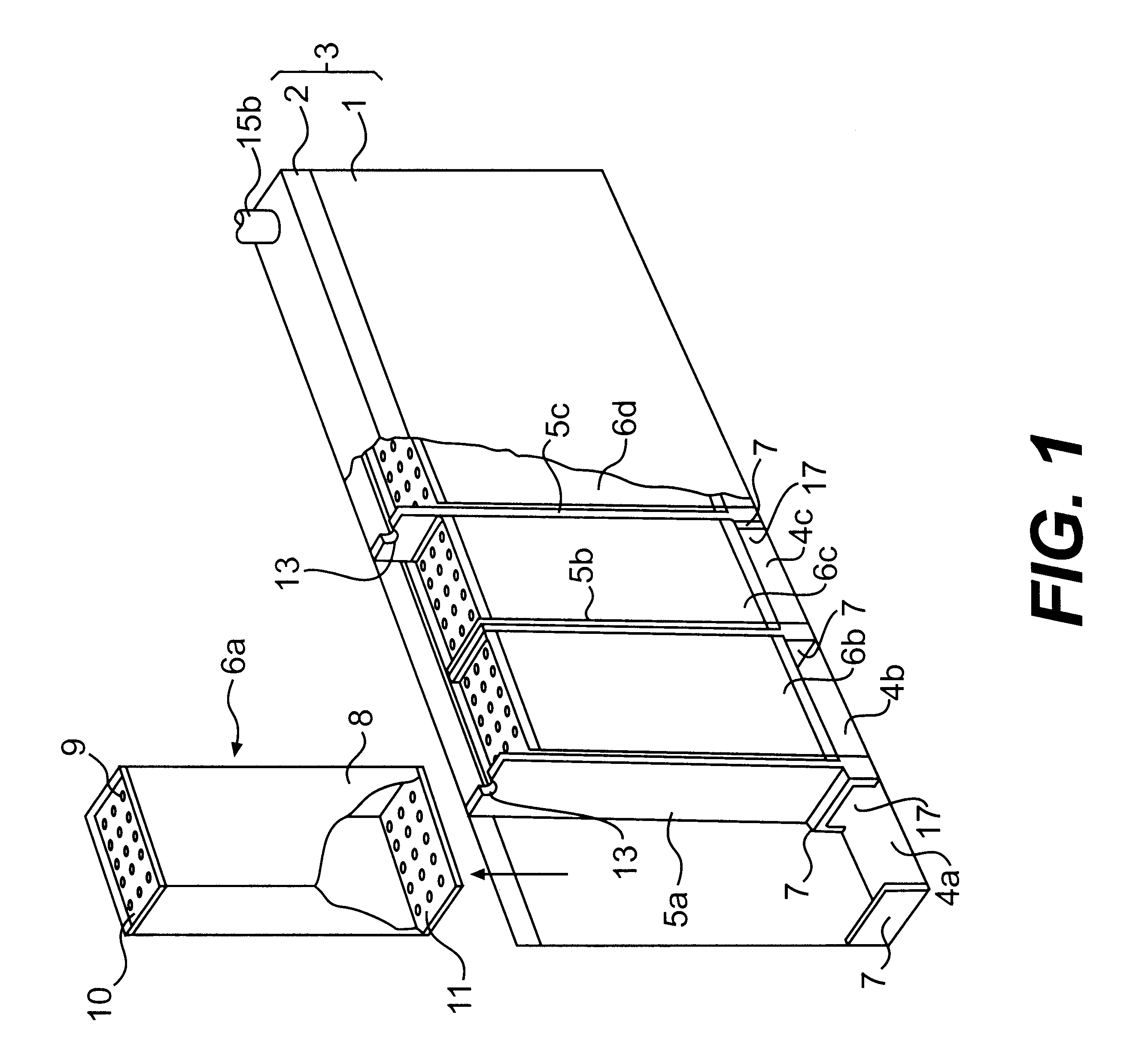
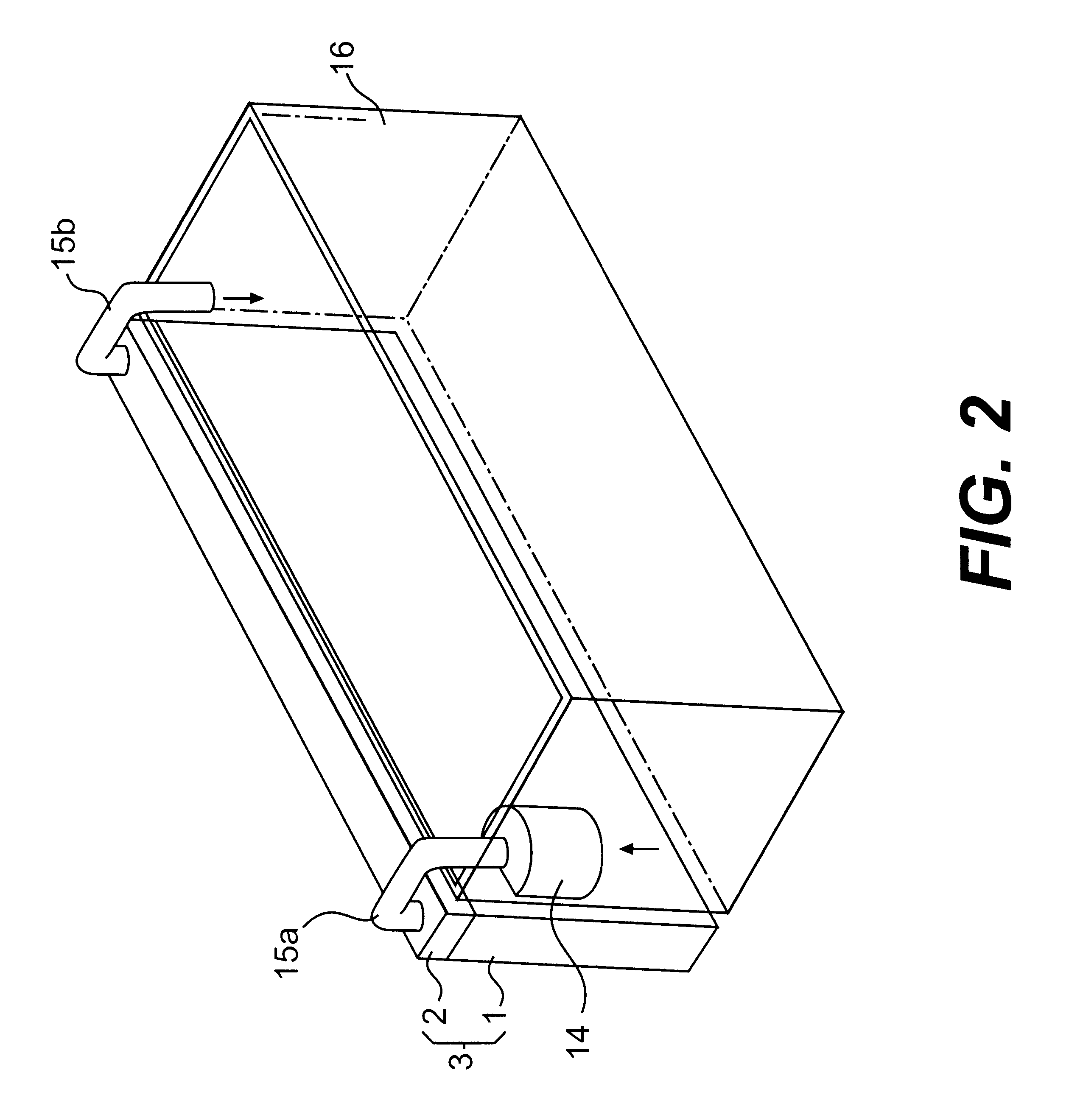
FIG. 1: a sketch showing partially cutaway perspective view of the first example of the actual application of this invention illustrating the aquarium filter equipment and FIG. 2 is a sketch of the installed filter equipment as described in FIG. 1 viewed perspectively.

This filter system consists of a two-part container (3) with an open thin box shaped casing (1) and a lid (2) to cover the opening. Within the casing are, for example six in this partial view sketch, vertical filtration chambers (4a.about.4f) separated by partitions (5a.about.5e) with three sides, base and two side edges, forming flush contact with the inside walls and the base of the casing. In each of the chambers (4a.about.4f) are replaceable cartridges for individual filter medium (6a.about.6f), partial view.

The partitions (5a.about.5e) for the chambers are positioned vertically in the casing (1) from the base to the lid (2) with some spacing between the top edge of the partition and the lid of the casing. There ar...

application example 2

Another example of the application of this invention can be described using FIG. 4 and FIG. 5. To avoid unnecessary repetition of information, descriptions that are the same as that of Example 1 will be indicated as such and not repeated.

FIG. 4: sketch of aquarium filter system Example 2: partially cutaway, perspective view FIG. 5: diagram of water flow through the interior of the FIG. 4 filter system: cross section

This filter system similar to the system above consists of a container (3) with casing (1) and lid (2), partitions (5a.about.5e), and cartridges for individual filter medium (6a.about.6f). The difference in this system from the previously described system is that the partitions 5a, 5c, and 5e do not have the opening (17). The upper edges of the partitions (5a.about.5e) are positioned at the same level. Using filter medium cartridge (6a) as an example, as illustrated in FIG. 4, the cartridge is constructed from side panel (8), perforated (9) top (10) and base (11) panels, ...


PUM

PropertyMeasurementUnit
Flow rateaaaaaaaaaa

Abstract

A filtration device for tank water for aquarium fish having several partitions dividing the casing into several filtration chambers. A removable filtration cartridge is inserted into each filtration chamber. The cartridge has top and bottom panels with perforations formed in the panels to allow water to flow through the cartridge. The partitions are arranged in an alternating pattern. One partition has an opening near the bottom of the casing, and the partition extends to the top of the casing. The next partition does not have an opening near the bottom of the casing and the partition does not reach the top of the casing. This arrangement allows water to flow through the filtration device in a zigzag pattern. The removable cartridges allow individual filter mediums to be replaced without removing all the beneficial bacteria from the system.

Description

TECHNICAL AREAThis invention pertains to aquarium water filtration equipment with its main focus on smaller equipment size, maximum reduction of water to filter medium contact surface and ease of filer medium installation and replacement.BACKGROUND TECHNOLOGYIn order to successfully raise and breed aquarium fish such as goldfish, fresh water tropical fish and marine fish it is necessary to use a filter devise capable of purifying the aquarium water by trapping and breaking down debris such as fish waste and excess fish food.A cross section diagram FIG. 6 is an example of a conventional filtering device, commonly called the open system. Medium such as glass wool (21) and ceramic beads (22) are layered to form a filtration layer. Water in the tank (23) is siphoned by a pump (24) then passing through multiple holes (not shown) in the sprinkler head (25) and sprayed over the filtration layer. First the larger debris is trapped by the glass wool (21), next the ceramic beads (22) function...

Claims


Application Information

Patent Timeline
IPC IPC(8): A01K63/04
CPCA01K63/045A01K63/04
Inventor TAKADA, SHUNSUKE
Owner TAKADA SHUNSUKE
Why Eureka
Try Eureka