Method and a system for putting a space vehicle into orbit, using thrusters of high specific impulse

a technology of high specific impulse and space vehicle, applied in the direction of attitude control, transportation and packaging, cosmonautic vehicles, etc., can solve the problems of increasing the financial burden, reducing the thrust provided for given consumption of electrical or thermal power, and limited power, so as to achieve low thrust and high specific impulse

Inactive Publication Date: 2001-04-10
SN DETUDE & DE CONSTR DE MOTEURS DAVIATION S N E C M A
View PDF8 Cites 26 Cited by
  • Summary
  • Abstract
  • Description
  • Claims
  • Application Information

AI Technical Summary

Benefits of technology

The present invention seeks to remedy the above-mentioned drawbacks and, in particular, to enable a satellite placed by a launcher or a space vehicle on an orbit that is not the nominal operational orbit of the satellite, and to reach said orbit in a manner that is particularly effective while using thrusters of high specific impulse and low thrust.
Another advantage associated with the present invention lies in the possibility of deploying the satellite completely or in part before its thrusters are put into operation. This is made possible because the high specific impulse thrusters deliver such low thrust that the drive thereof does not generate stresses that could damage fragile structures such as solar panels or solar concentrators, or deployable antennas and masts.

Problems solved by technology

On a satellite, such power is limited by the size of its solar panels, by the size of its solar thermal energy concentrators, or by the size of its radioisotopic generator, or indeed by the size of its energy storage means.
Thus, the greater the specific impulse of thrusters, the lower the thrust provided for given consumption of electrical or thermal power.
The longer the total duration of the transfer maneuver, the greater the financial burden, and costs associated with putting the vehicle into orbit also increase (including ground station costs and the cost of tracking teams on the ground).
Also, a long duration transfer maneuver increases the risk of the space vehicle being damaged as it passes through the Van Allen belts (which vary in position, but which may be situated, for example, in the vicinity of the following altitudes: 1800 km, 2000 km, 10,000 km, and 21,000 km).
Also, the number of times the engine needs to be started is also large and this can give rise to major operational constraints.
This means that any procedure for putting the satellite into orbit that requires thrusters to be started on numerous occasions cannot be performed safely using only one ground station.
However, under such circumstances, for given power delivered to the thrusters, the specific impulse would have to be smaller and consequently the mass consumed during the maneuver would be greater.
The various solutions that have already been recommended for putting a satellite into orbit in this manner are therefore of relatively low performance.
Nevertheless, the number of revolutions in the Van Allen belts cannot be optimized, which is a drawback, and above all, at present that type of maneuver applies only to transfers between orbits that are circular or, where appropriate, between particular elliptical orbits.
If use is made only of high specific impulse and low thrust propulsion, that technique for putting a satellite into orbit is of relatively low performance, particularly in terms of duration.
The number of revolutions that pass through the Van Allen belts is high and the number of times the thrusters are started is large, and unfortunately this large number of thruster starts is necessary during the first stage during which perigee altitude is increased, and in which the sidereal period is, in particular, different from the sidereal period of rotation of the earth.
However, the mass consumed during the maneuver is relatively large, and above all two different types of propulsion system need to be present, thereby increasing cost compared with systems having only one type of propulsion system, making the architecture of the satellite more complex, and increasing preparation and launch costs, in particular because of the need to fill various tanks with different substances and because of the precautions that need to be taken against the risks of pollution or of fire.

Method used


Image

  • Method and a system for putting a space vehicle into orbit, using thrusters of high specific impulse
  • Method and a system for putting a space vehicle into orbit, using thrusters of high specific impulse
  • Method and a system for putting a space vehicle into orbit, using thrusters of high specific impulse

Examples


Embodiment Construction

Three conventional methods that have already been proposed for placing a satellite on a circular orbit, and they are recalled initially with reference to FIGS. 1 to 3.

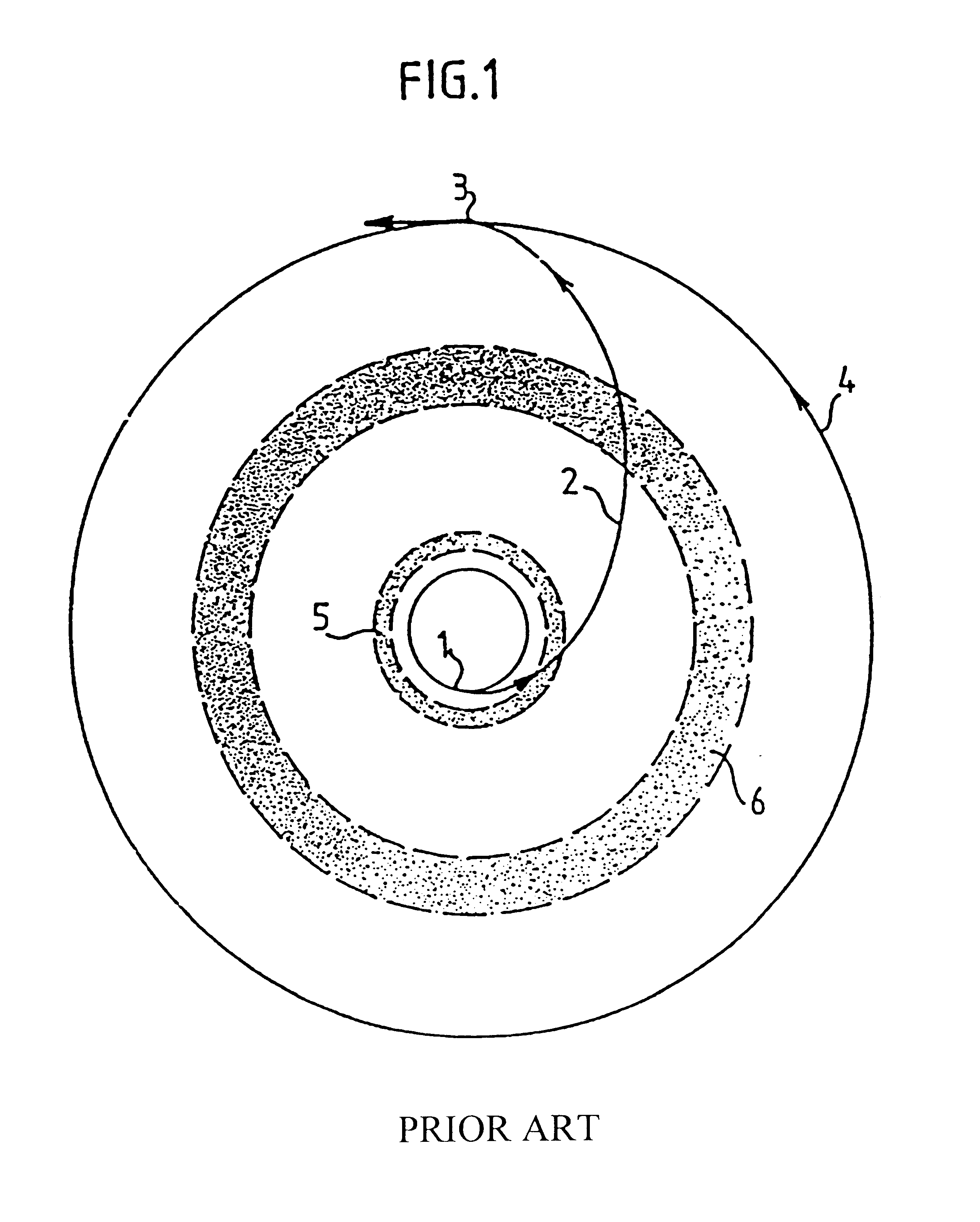
FIG. 1 is a diagram of the various stages in the Hohmann maneuver, comprising a launch stage 1 during which the rocket places a satellite on a low orbit, followed by a transfer stage 2 during which the satellite is injected by an increase of speed at perigee onto an elliptical orbit whose apogee corresponds to the desired final altitude, and at which a second increase of speed 3 serves to inject the satellite onto a final circular orbit 4. Portions referenced 5 and 6 represent zones of intense radiation known as the Van Allen belts.

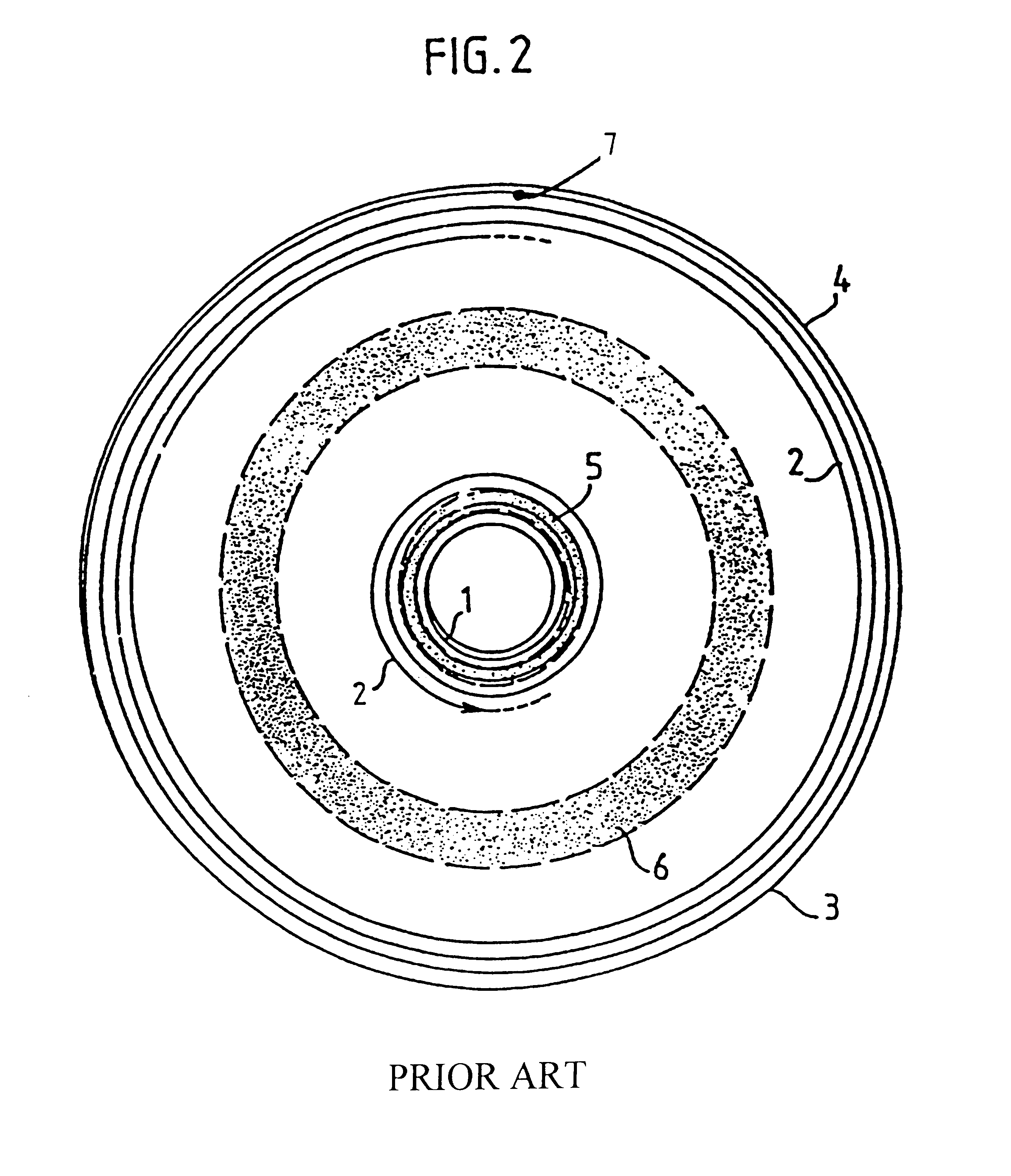
FIG. 2 shows the use of a spiral trajectory implementing acceleration that is very low, but continuous. There can be seen the stage 1 of launching into low circular orbit, and the transfer stage 2 which is constituted by the spiral orbit proper. Reference 7 shows the location where spiral fi...


PUM


Abstract

The method serves to place a space vehicle, such as a satellite, on a target orbit such as the orbit adapted to normal operation of the space vehicle and starting from an elliptical initial orbit that is significantly different from, and in particular more eccentric than the target orbit. The space vehicle is caused to describe a spiral trajectory made up of a plurality of intermediate orbits while a set of high specific impulse thrusters mounted on the space vehicle are fired continuously and without interruption, thereby causing the spiral trajectory to vary so that on each successive revolution, at least during a first stage of the maneuver, perigee altitude increases, apogee altitude varies in a desired direction, and any difference in inclination between the intermediate orbit and the target orbit is decreased, after which, at least during a second stage of the maneuver, changes in perigee altitude and in apogee altitude are controlled individually in predetermined constant directions, while any difference in inclination between the intermediate orbit and the target orbit continues to be reduced until the apogee altitude, the perigee altitude, and the orbital inclination of an intermediate orbit of the space vehicle have substantially the values of the target orbit.

Description

The present invention relates to a method of putting a space vehicle, such as a satellite, into a target orbit such as the orbit for normal operation of the space vehicle, starting from an elliptical initial orbit that is significantly different and in particular more eccentric than the target orbit.PRIOR ARTMost artificial satellites are now fitted with a thruster system enabling them to move in space, in particular to correct imperfections of trajectory, due in particular to imperfections with which they were put into orbit, to the gravitational attraction of the moon and the sun, to potential effects due to the earth being non-spherical, to aerodynamic, magnetic, and electrical effects associated with the earth, and to the action of solar radiation. The thrust system of a satellite also enables the satellite to be put on station, to make changes to its orbit, to ensure that it is appropriately oriented in space, or indeed to ensure that the attitude control system remains functio...

Claims


Application Information

Patent Timeline
Patent Type & Authority Patents(United States)
IPC IPC(8): B64G1/00B64G1/24B64G1/22B64G1/40B64G1/26G05D1/08
CPCB64G1/002B64G1/007B64G1/242B64G1/405B64G1/2427
Inventor KOPPEL, CHRISTOPHE
Owner SN DETUDE & DE CONSTR DE MOTEURS DAVIATION S N E C M A
Why Eureka
Try Eureka