Suction device for boundary layer control in an aircraft

a technology of suction device and aircraft, which is applied in the direction of boundary layer control, engine fuction, wings, etc., can solve the problems of specialized construction of aircraft engine or engine, inability to achieve adequate suction flow, and inability to provide the required suction flow

Inactive Publication Date: 2001-04-17
DAIMLER CHRYSLER AEROSPACE AIRBUS
View PDF12 Cites 60 Cited by
  • Summary
  • Abstract
  • Description
  • Claims
  • Application Information

AI Technical Summary

Problems solved by technology

The prior art has not been able to provide an economical and easily adaptable system using one or more suction sources to achieve suction and control of the boundary layer air flow over relatively large surface areas of an aircraft, using the high mass flow of air being moved by an air breathing engine, such as the bypass flow of a high bypass ratio fanjet or turbofan engine, as the primary driving force for the suction generati

Method used


Image

  • Suction device for boundary layer control in an aircraft
  • Suction device for boundary layer control in an aircraft
  • Suction device for boundary layer control in an aircraft

Examples


Embodiment Construction

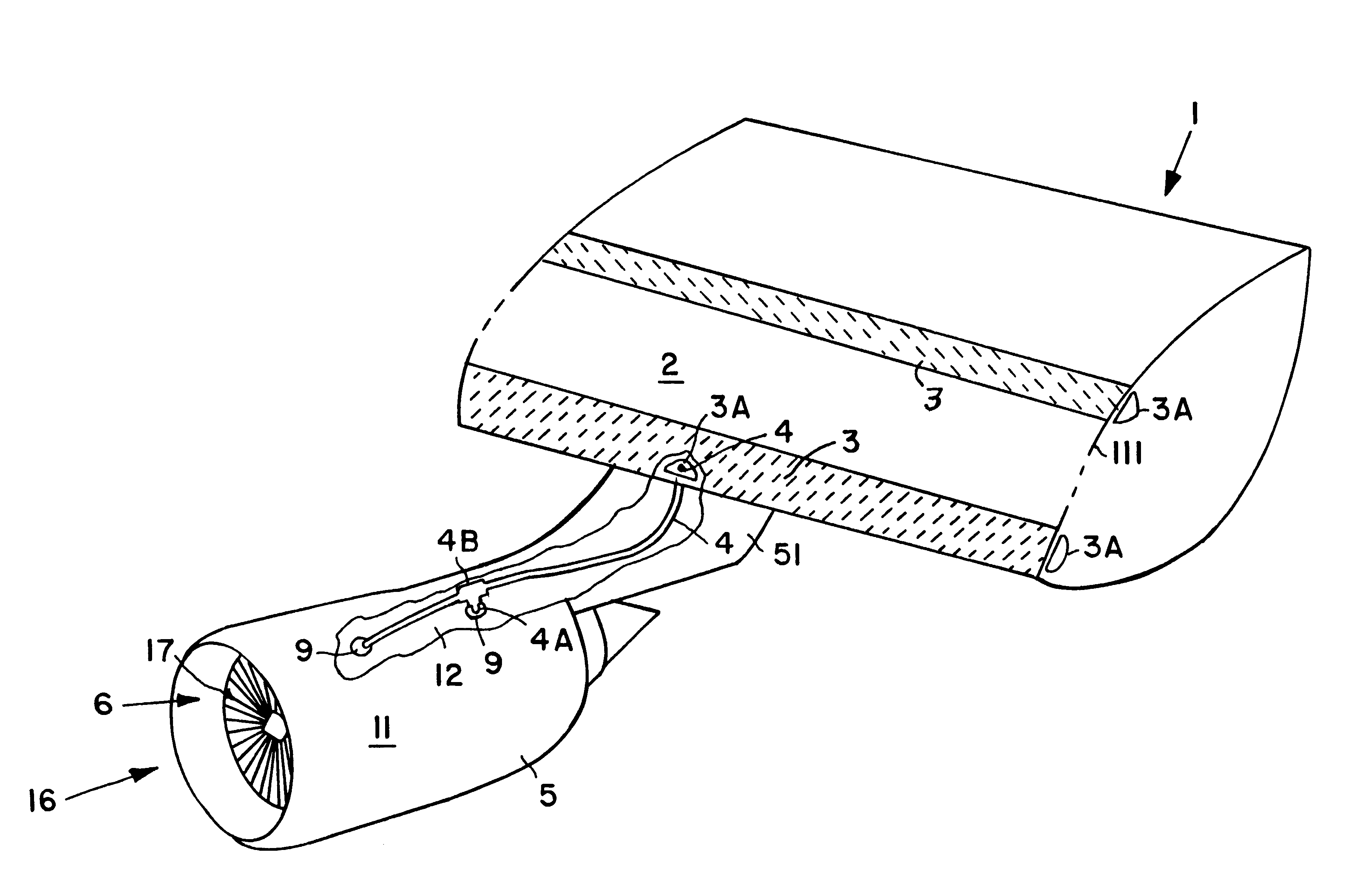
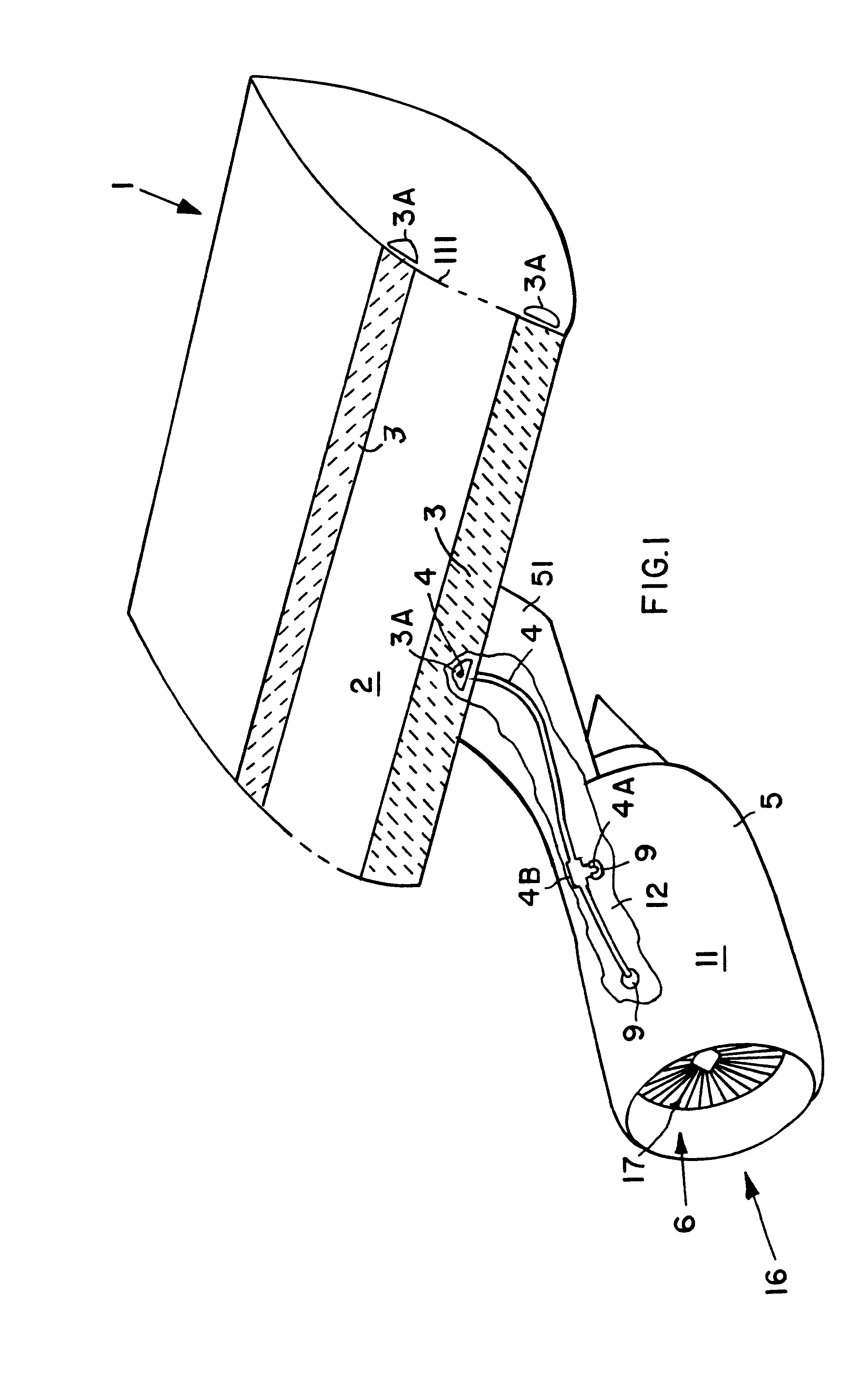
As shown in FIG. 1, an aircraft, generally indicated by reference number 1, includes a wing 111 with an outer skin 2. At least certain flow critical areas of the outer skin 2 are embodied as suction areas 3, such as an area along the leading edge and an area prone to flow separation and shock formation extending spanwise along a top low pressure area of the wing at a spacing aft of the leading edge. Additional suction areas can be provided on other areas of the outer skin of the aircraft, for example at areas of the fuselage and / or stabilizers at which a boundary layer control is needed.

The suction areas 3 are formed with a porous skin material, or a skin having a great number of perforations or holes therethrough, in communication with suction channels 3A underneath the skin. Thereby, application of a suction vacuum to the suction channels 3A will suck air, and particularly a portion of the air forming a boundary layer over the outer skin 2 of the wing 1, through the porous or perf...


PUM


Abstract

A system for achieving a boundary layer control by sucking at least a portion of the boundary layer air flow through perforated or porous suction areas on the outer skin of the wings or other areas of the aircraft, includes one or more jet pumps (7) arranged in the bypass engine (5) of the aircraft, and a system of suction conduits (4) connecting the jet pumps (7) to suction channels (3A) communicating with the perforated or porous suction areas (3). Each jet pump (7) includes an ejector pipe (101) that is driven by an external surrounding driving jet (8) or by an internal driving jet (8) flowing through an internal jet pipe (15). The jet pumps (7) are arranged at selected locations in the air intake upstream of the fan, in the bypass channel (18) just downstream of the fan, in the bypass channel near the outlet end thereof, in the core hot gas channel (19) upstream of a compressor assembly, and/or in the core channel downstream of a turbine assembly. The jet pumps (7) provide an efficient, maintenance-free, reliable, and easily installable suction generator system.

Description

The invention relates to a system for generating a suction air flow for sucking off at least a portion of the boundary layer air flow at least at the flow critical areas on the outer skin of an aircraft, and thereby controlling the boundary layer and particularly a shock boundary layer so as to maintain a laminar boundary layer flow.BACKGROUND INFORMATIONIt is generally known that it is possible to reduce aerodynamic friction resistance and overall drag on the skin of an aircraft, by sucking away at least a portion of the air forming the boundary layer along the aerodynamic surfaces of the outer skin of the aircraft, especially at flow critical areas. Various embodiments and configurations of systems for achieving such boundary layer control by suction are known in the art. For example, German Patent Laying-Out Publication DE-AS 1 280 057 discloses a system for sucking boundary layer air away from an aircraft wing, wherein a suction source located in the interior of the aircraft is ...

Claims


Application Information

Patent Timeline
IPC IPC(8): B64C21/00B64C21/06
CPCB64C21/06F05B2260/601Y02T50/166B64C2230/04B64C2230/22Y02T50/10
Inventor PFENNIG, JUERGENMEISTER, JUERGEN
Owner DAIMLER CHRYSLER AEROSPACE AIRBUS
Why Eureka
Try Eureka