Displacement fluid machine

a fluid machine and displacement technology, applied in the direction of machines/engines, rotary/oscillating piston pump components, liquid fuel engines, etc., can solve the problems of lowering performance, provoking vibration and noise problems, and reducing performance, so as to improve performance, improve performance, and improve the effect of sealing

Inactive Publication Date: 2001-04-17
HITACHI JOHNSON CONTROLS AIR CONDITIONING INC
View PDF19 Cites 9 Cited by
  • Summary
  • Abstract
  • Description
  • Claims
  • Application Information

AI Technical Summary

Benefits of technology

In an orbiting fluid machine in which a displacer has a relatively flattened shape, it is thought that the lowering of the performance described above is attributable to a poor seal in a gap (gap in the axial direction) between the displacer and each end plate. According to the present invention described above, there can be provided the orbiting fluid machine in which an internal leakage of the working fluid through the axial gap between the displacer and each end plate, which is caused by the pressure difference between the compression operation chambers within the cylinder and a suction chamber, is greatly reduced, thereby enhancing the performance. And besides, an internal leakage of the working fluid through gaps in sliding portions of the displacer and the cylinder, which jointly form the operation chambers, can also be suppressed, and therefore a fluid loss and a mechanical friction loss is reduced, and there can be provided the displacement fluid machine of a high efficiency.

Problems solved by technology

The reciprocating fluid machine has an advantage that it can be easily manufactured, and is inexpensive since its construction is simple, but a stroke from the end of the suction to the end of the discharge is as short as 180.degree. in terms of an angle of rotation of a shaft, and the flow velocity during the discharge stroke becomes high, which invites a problem that the performance is lowered because of an increased pressure loss.
And besides, since the motion for reciprocating the piston is required, the rotation shaft system can not be perfectly balanced, which invites a problem that large vibrations and noises are produced.
However, a fluid is discharged for each rotation of the shaft, and therefore a variation in a gas compression torque is relatively large, which invites vibration and noise problems as in the reciprocating fluid machine.
However, it is necessary to control a clearance between the volute wraps, engaged with each other, as well as a clearance between the end plate and the tip of the wrap, and therefore high-precision processing or working is needed, which invites a problem that the processing cost is high.
And besides, since the stroke from the end of the suction to the end of the discharge is as long as more than 360.degree. in terms of the rotational angle of the shaft, the time for the compression stroke is long, which invites a problem that an internal leakage increases.
These fluid machines are so designed that a pressure pulsation of the working fluid can be reduced so as to reduce a variation in torque, but have not yet matured to a displacement fluid machine sufficiently suited for practical use.
However, the stroke from the end of the suction to the end of the discharge in each of the operation chambers, formed by the plurality of vanes of the piston and the cylinder, is as short as about 180.degree. in terms of the angle .theta. of rotation of the shaft (This is about a half of that of the rotary type, and is about the same as that of the reciprocating type), and therefore the flow velocity of the fluid becomes high during the discharge stroke, so that a pressure loss increases, which invites a problem that the performance is lowered.
However, in the structure disclosed in the above documents 1 and 2, the compression operation chambers, formed during the stroke from the end of the suction to the end of the discharge, are disposed in a concentrated manner on one side of the drive shaft, and therefore the rotation moment, acting on the displacer, becomes excessive, so that the vanes are subjected to friction and wear, which invites a problem that the performance and reliability are affected.
As a result, there has been encountered a problem that the compression performance (considered equivalent to the pumping performance) is lowered when the rotational speed exceeds a certain value.

Method used


Image

  • Displacement fluid machine
  • Displacement fluid machine
  • Displacement fluid machine

Examples


Embodiment Construction

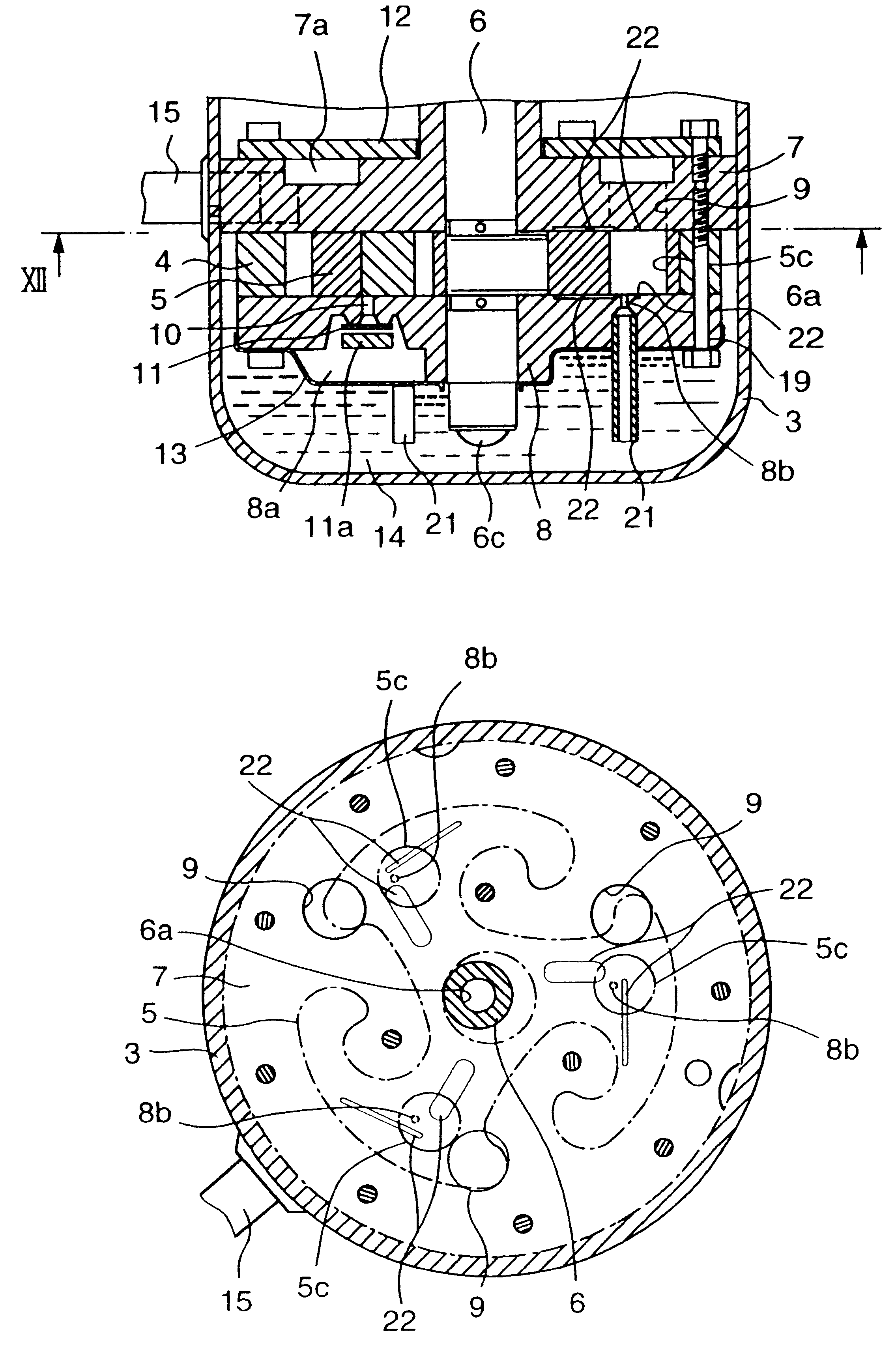
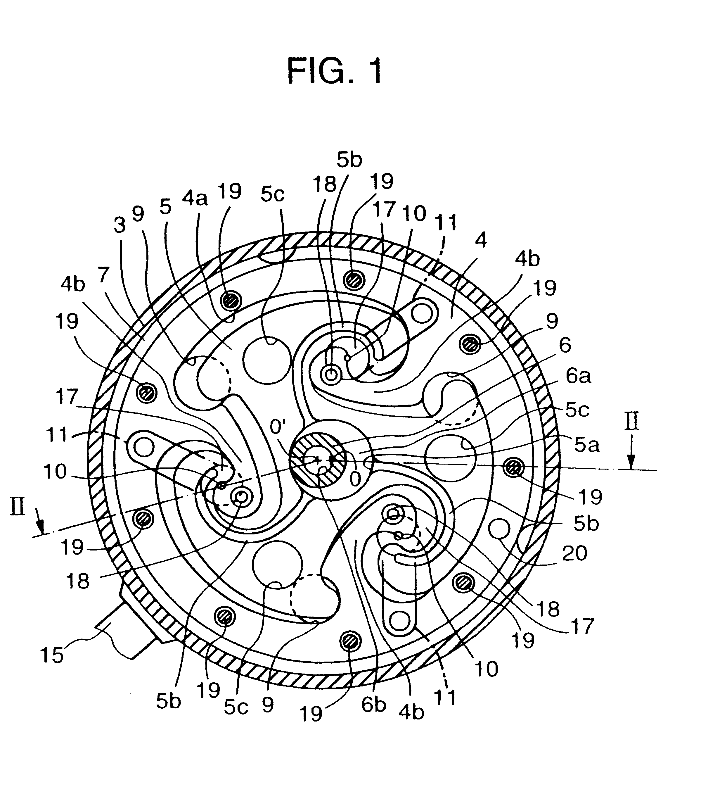
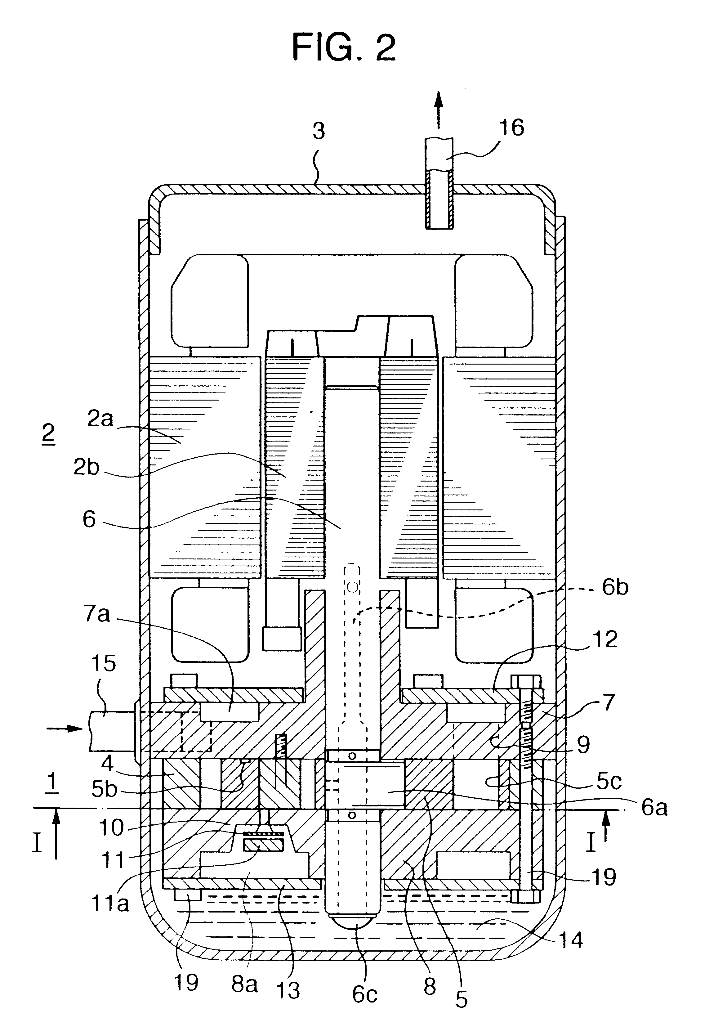
A preferred embodiment of the present invention will now be described in detail with reference to the drawings. FIG. 1 is a cross-sectional view of a hermetic-type compressor using an orbiting fluid machine according to a preferred embodiment of the invention, FIG. 2 is a cross-sectional view taken along the line II--II of FIG. 1, FIG. 3 is a plan view showing the principle of the operation of the compressor using an orbiting fluid machine in accordance with the invention, FIG. 4 is a plan view of a displacer in accordance with the invention, FIG. 5 is a cross-sectional view taken along the line V--V of FIG. 4, FIG. 6 is a plan view of a casing for engagement with the displacer, FIG. 7 is a cross-sectional view taken along the line VII--VII of FIG. 6, and FIG. 8 is a view explaining the formation of an oil film at an end surface of the displacer.

In FIG. 2, reference numeral 1 denotes an orbiting compression element of the invention, reference numeral 2 an electrically-operating elem...


PUM


Abstract

An orbiting fluid machine has a feature that the speed of sliding movement is low, while vibrations are small, its performance is lowered when the rotational speed becomes high, and this problem is resolved by the following structure. A displacement fluid machine includes a displacer making an orbital motion within a casing into which a working fluid is drawn, thereby drawing and discharging the working fluid, in which an oil retaining mechanism or a seal mechanism is provided at each of opposite end surfaces of the displacer. This results that, axial gaps at the end surfaces of the displacer are effectively sealed so as to reduce a leakage loss, thereby achieving a high performance and a high reliability.

Description

BACKGROUND OF THE INVENTION1. Field of the InventionThis invention relates to a high-efficiency displacement fluid machine in which a displacer for moving a working fluid revolves, i.e. makes an orbital motion, with a substantially constant radius relative to the cylinder, into which the working fluid has been drawn, without rotation, thereby conveying the working fluid.2. Description of the Related ArtAs displacement-type fluid machines, there have been long known a reciprocating fluid machine in which a piston is reciprocally moved repeatedly in a cylinder to move a working fluid, a rotary (rolling piston-type) fluid machine in which a cylindrical piston makes an eccentric rotary motion in a cylinder to move a working fluid, and a scroll fluid machine in which a pair of stationary and orbiting scrolls, each having a lap of a volute configuration formed perpendicularly on an end plate, are engaged with each other, and a working fluid is moved by revolving the orbiting scroll.The re...

Claims


Application Information

Patent Timeline
Patent Type & Authority Patents(United States)
IPC IPC(8): F01C1/04F01C1/00F04C18/04F04C27/00F04C29/02F04C29/00
CPCF01C1/04F04C18/04F04C27/008F04C29/023F04C18/02F04C27/005F04C29/028
Inventor KOHSOKABE, HIROKATSUTAKEBAYASHI, MASAHIROMITSUYA, SHUNICHIHATA, HIROAKIOSHIMA, KENICHIOSHIMA, YASUHIRO
Owner HITACHI JOHNSON CONTROLS AIR CONDITIONING INC
Why Eureka
Try Eureka