Multiple stage high efficiency rotary filter system

a rotary filter and multi-stage technology, applied in the field of unique two-element filter, can solve the problems of high cost, complicated internal construction, health hazards, etc., and achieve the effect of reducing caking or blinding of the filter media, constant negative pressur

Inactive Publication Date: 2001-04-17
TONEY JERRY L +2
View PDF5 Cites 83 Cited by
  • Summary
  • Abstract
  • Description
  • Claims
  • Application Information

AI Technical Summary

Benefits of technology

A further object of the invention is to provide an improved method of operating a filter with increased capacity and efficiency at relatively low energy and capital cost and with a minimum of complexity.
The downstream end of the drum abuts the downstream inside end of the enclosure. A rotary seal is used to prevent contaminated process air from entering the clean air stream exiting the drum filter through a duct which leads to a variable speed balancing fan. This fan maintains a relatively constant negative pressure within the enclosure.

Problems solved by technology

Also the current prevalence of superabsorbent polymers (SAP) added to the pads can create a health hazard if present in the plant air.
These disadvantages include high cost limited versatility in terms of materials filtered, complicate internal construction, need for frequent maintenance shutdowns, difficulty in handling super absorbent polymer (SAP) fractions and difficulties in adapting to recycle operation.
The last two problems are especially important in the large market of disposable diapers where the fluff pulp that is returned to the process represents a substantial cost savings to the manufacturer.
If the volume of air moving through the forming chamber and its pressure are not consistent pad formation will be poor.
If the air volume or pressure is changed, the pad will have different thicknesses, densities and absorbencies and will not meet the user's specifications.
Drum filters are expensive and take up a large amount of floor space in a plant.
Using one drum filter or other filter configuration for two or more production lines in order to handle larger amounts of fluff has not been an adequate solution to the problem.
In this case uniform air volume and pressure will not be maintained if any of the connected production lines cease to operate.
Systems which can handle the higher loads without shutdown problems are expensive and quite complex to operate and maintain.
Another problem found in the rotary drum and other filter systems is that waste pulp has a tendency to accumulate in the bottom and other parts of the filter enclosure.
Gravity and dead air spots cause the waste to remain in these corner areas Further, fluff sticks to the accumulated fluff which exacerbates the problem.
Frequent shutdowns are required to clean out this fluff accumulation which is expensive and undesirable.
However, it has been found that generally these solutions do not solve the fluff accumulation problem.
Fluff accumulation can cause other problems in a filter system.
Regardless of the limit set accumulated fluff pulp in the enclosure is a genuine safety threat.
The structure and installation of the explosion vent and its duct work can often be more elaborate and more expensive than the filter.

Method used


Image

  • Multiple stage high efficiency rotary filter system
  • Multiple stage high efficiency rotary filter system
  • Multiple stage high efficiency rotary filter system

Examples


Embodiment Construction

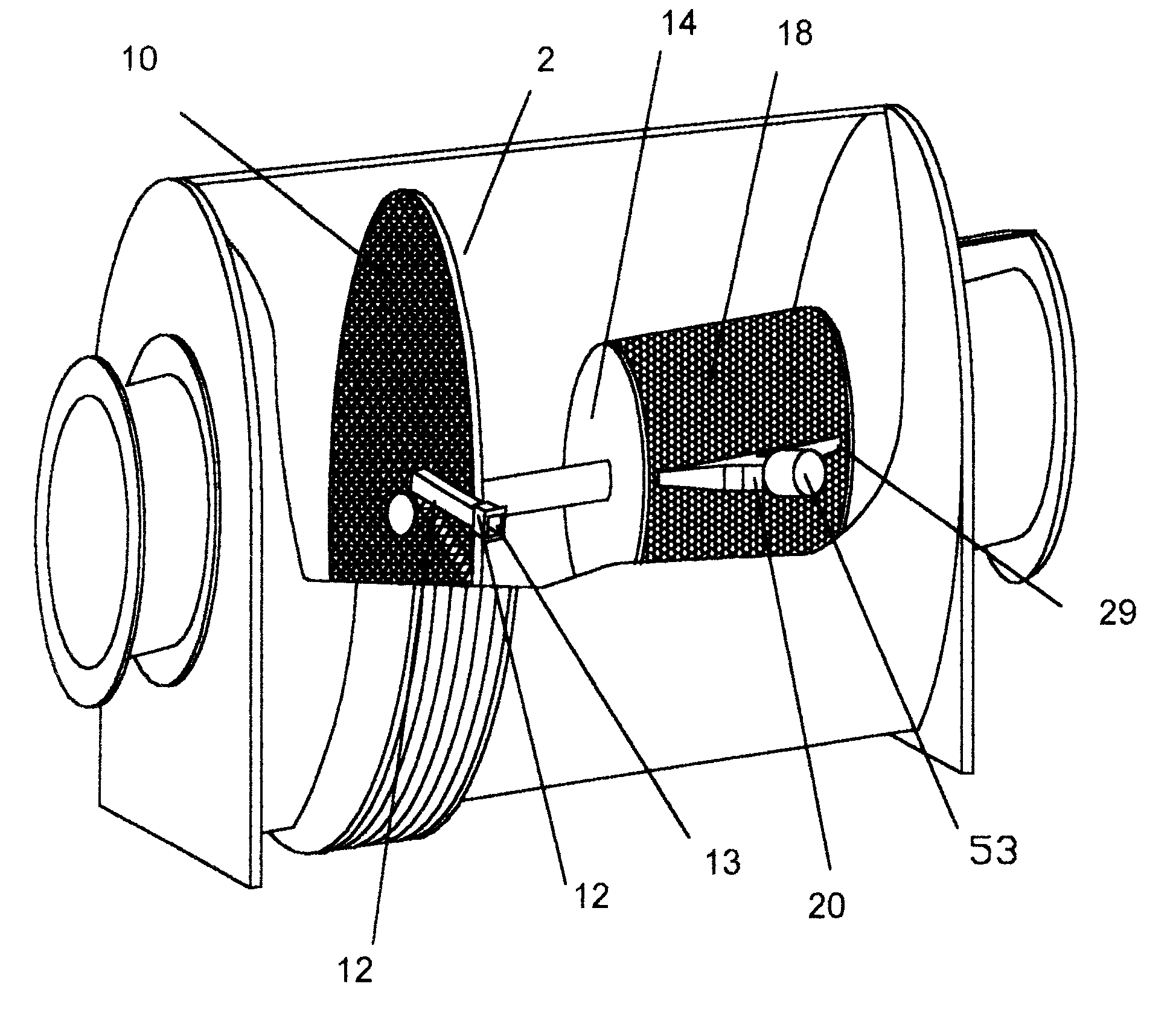
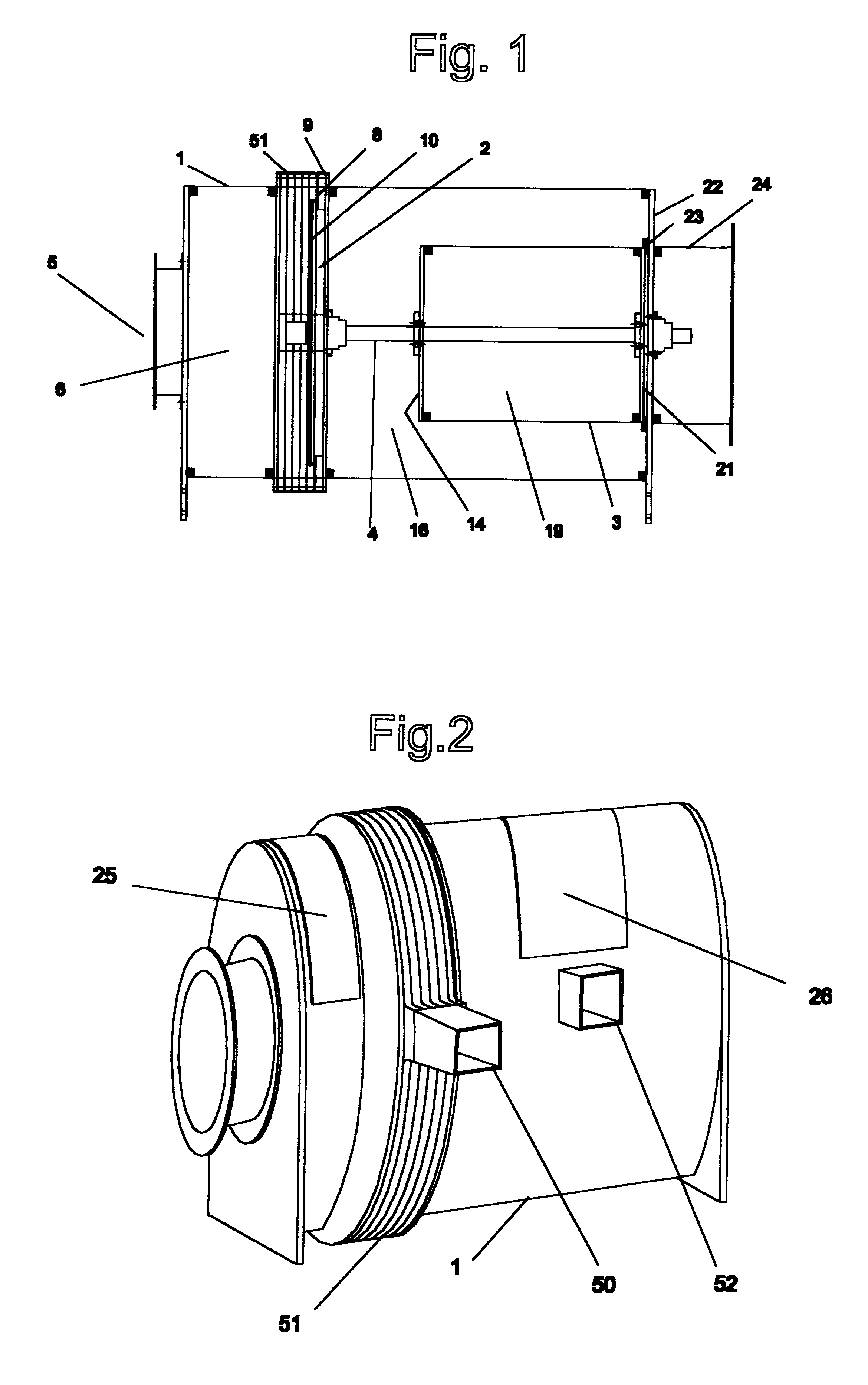
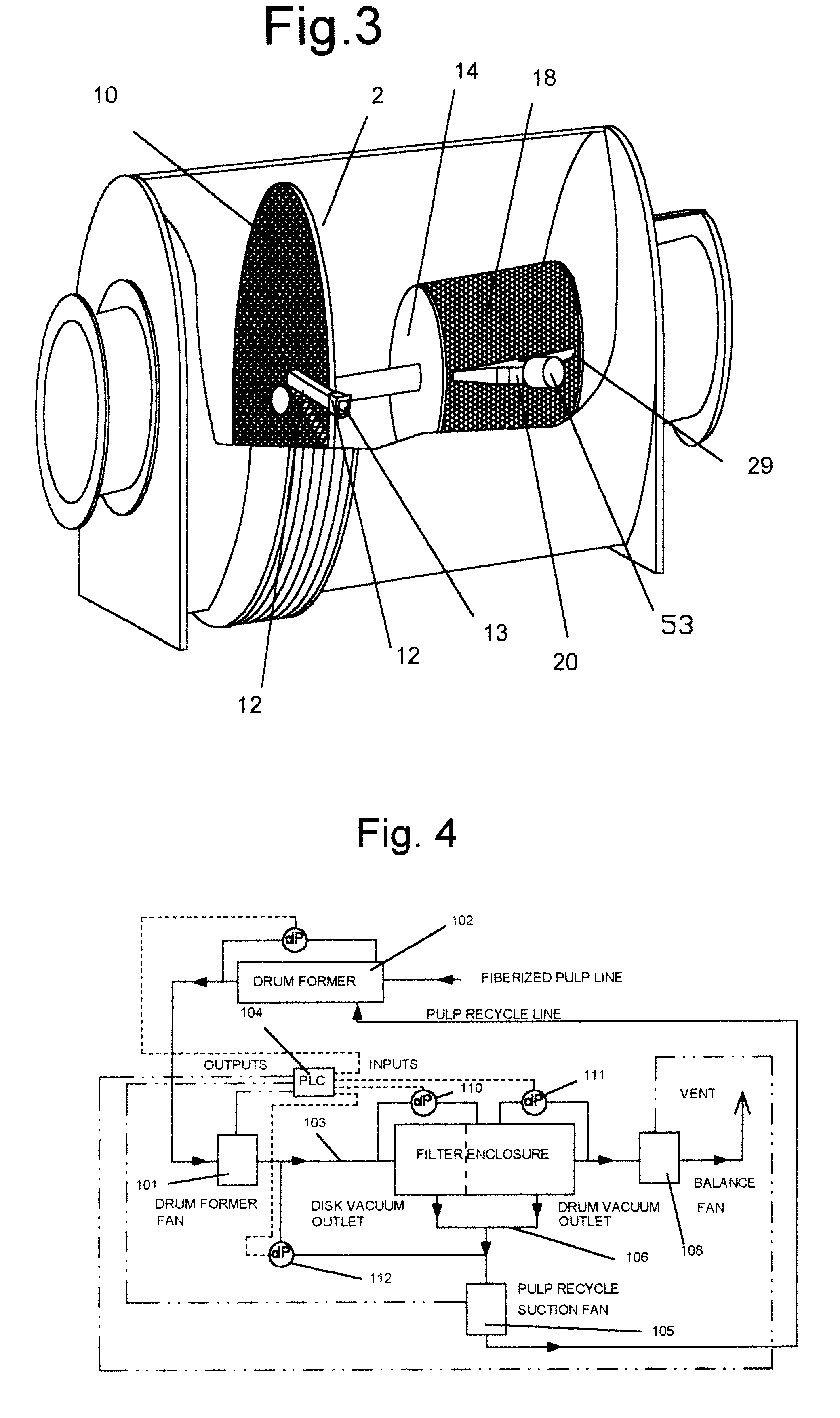
Referring to FIG. 1 discloses a filter assembly comprising a tubular filter enclosure 1 containing a rotary disk 2 and a drum filter 3 attached to a common shaft 4 within the enclosure 1. The process air and entrained pulp 5 are introduced into the primary plenum 6, created between the first end of the enclosure 7 and the rotary disk 2. As shown in FIG. 4 it enters through duct 103 from the pad former process suction fan 101 of FIG. 4. which is located between the filter and the pad former 102.

The rotary disk 2 extends radially from the shaft to slightly beyond the inside diameter of the sealing ring 9. A seal is formed by a felt seal 8 fixed to the down stream surface of the disk and between the disk and the sealing ring 9. While the preferred embodiment is described with reference to a seal and sealing ring it is to be understood that a variety of rotary filter disk sealing configurations may be used. The rotary disk 2 is detachably connected to the shaft by a connection means and...


PUM

PropertyMeasurementUnit
distanceaaaaaaaaaa
distanceaaaaaaaaaa
diameteraaaaaaaaaa

Abstract

An apparatus and method for filtration of particulate matter in fluid streams. A unique high efficiency, two element filter embodying an enclosure containing a tandem rotary disk and drum filter mounted on a common shaft is described. A method of operation including manual and computer control modes are described.

Description

1. Field of the InventionThis invention relates in general to a unique two element filter embodying an enclosure containing a tandem rotary disk and drum filter, and more specifically is directed to a high efficiency, low residence time system which has both the disk filter and the drum filter in line on the same shaft. Its design permits the filtration media to be changed in less than 10 minutes for different systems or maintenance.2. Background of the InventionThe main absorbent component of most disposable sanitary products such as diapers and sanitary napkins is the pad or core. Typically the pad is made of wood pulp that has been fiberized by a special mill, designed to handle a special absorbent grade of wood pulp. After the pulp is fiberized, it is drawn out of the mill by an air stream onto a pad former which contains a number of shaped air forming pockets with integral screens.The screens are generally between 20 and 80 mesh. The pad is formed on the screen with its weight ...

Claims


Application Information

Patent Timeline
Patent Type & Authority Patents(United States)
IPC IPC(8): B01D46/26B01D46/24B01D33/073B01D33/06
CPCB01D33/073B01D46/26B01D33/15B01D33/42
Inventor TONEY, JERRY L.TONEY, NATHAN E. E.WARD, GREGORY F.
Owner TONEY JERRY L
Why Eureka
Try Eureka