Cathode cylinder for use in metal-air fuel cell battery systems and method of fabricating the same

a fuel cell battery and cathode cylinder technology, which is applied in the direction of primary cell maintenance/service, cell components, secondary cell servicing/maintenance, etc., can solve the problems of increasing the electrical power required, increasing the likelihood of damage (or destruction) to the surface of the cathode structure and metal-fuel tape, and increasing the likelihood of damag

Inactive Publication Date: 2001-04-17
REVEO
View PDF57 Cites 13 Cited by
  • Summary
  • Abstract
  • Description
  • Claims
  • Application Information

AI Technical Summary

Benefits of technology

Accordingly, it is a primary object of the present invention to provide an improved metal-air fuel cell battery (FCB) system which avoids the shortcomings and drawbacks of prior art systems and methodologies.
Another object of the present invention is to provide a system, wherein the metal-fuel tape, cathode structures and ionically-conductive medium are moved relative to each other so that frictional forces generated among the metal-fuel tape, cathode structures and ionically-conductive medium are substantially reduced, thereby reducing the amount of electrical power required to drive the cathode, metal-fuel tape and ionically-conductive medium and transport mechanisms, and decreasing the likelihood of damage to the cathode structure and metal-fuel tape, and permit reuse thereof over a large number of cycles without replacement.

Problems solved by technology

The greatest limitation, however, with prior art metal-air FCB systems is that, as the metal-fuel tape is being transported over the stationary cathode structures within such systems, frictional (e.g. shear) forces are generated, causing a number of problems to arise.
One problem is that such frictional forces cause an increase in the amount of electrical power required to transport the metal-fuel tape through the system.
Another problem is that such frictional forces cause metal-oxide particles to be shed from metal-fuel tape during transport and to become embedded within the porous structure of the cathode, thereby preventing ionic transport between the cathode and ionically-conductive medium (i.e. referred to as "blinding"), and increasing the likelihood of damage (or destruction) to the surface of the cathode structure and metal-fuel tape.
Overall, such problems tend to reduce the operational efficiency of prior art metal-air FCB systems, as well as the life of the cathode structures and metal-fuel tape employed therein.

Method used


Image

  • Cathode cylinder for use in metal-air fuel cell battery systems and method of fabricating the same
  • Cathode cylinder for use in metal-air fuel cell battery systems and method of fabricating the same
  • Cathode cylinder for use in metal-air fuel cell battery systems and method of fabricating the same

Examples


second embodiment

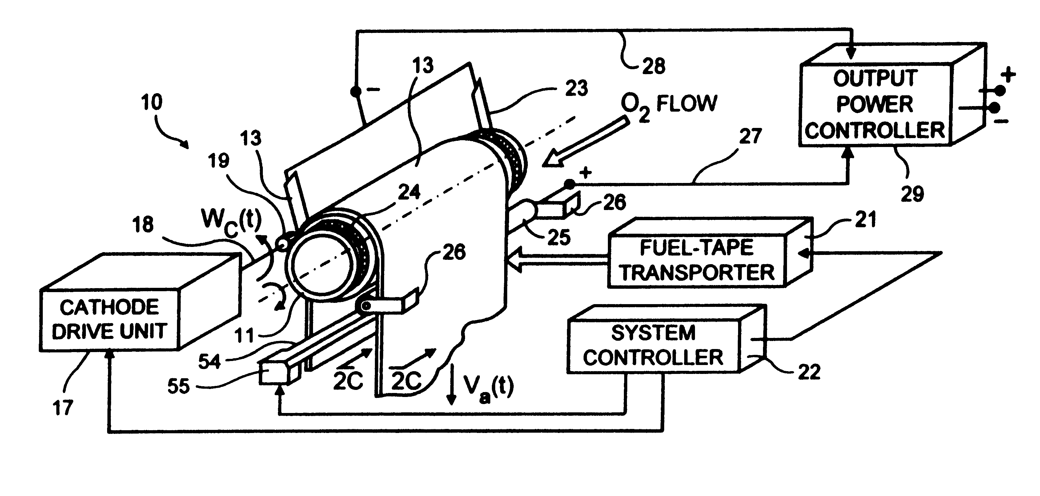
FIG. 3 is a second illustrative embodiment of the FCB system, wherein metal-fuel tape is passed over the cylindrical cathode structure hereof which is driven an angular velocity equalized to the velocity of the metal-fuel tape, and wherein the anode-contacting structure engages the inner surface of the metal-fuel tape and the metal-fuel tape has an ionically-conductive coating applied thereon;

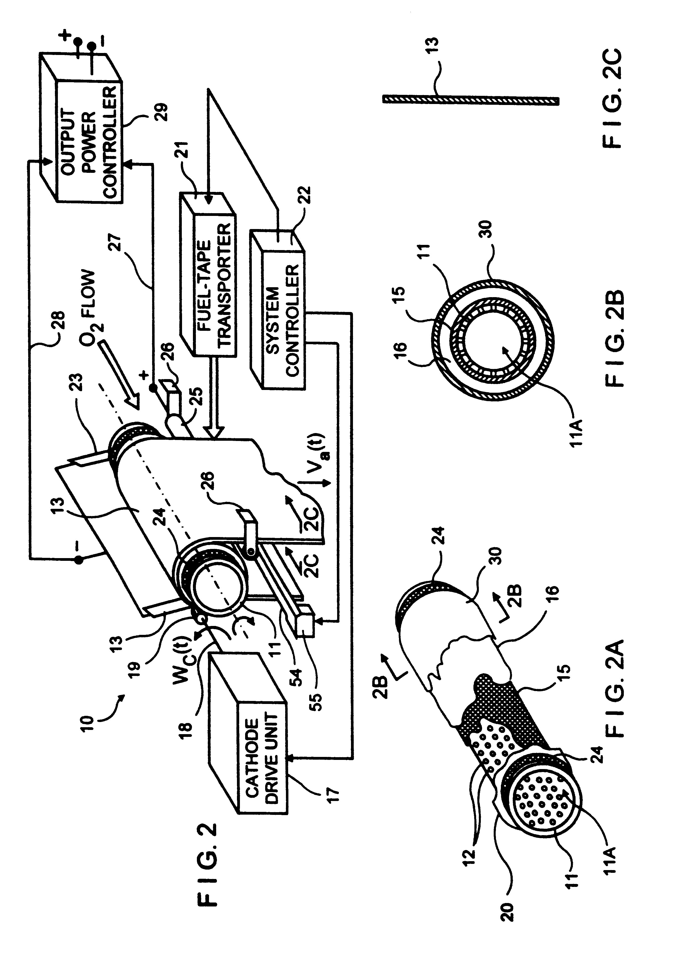
FIG. 3A is a partially broken away perspective view of the cylindrical cathode structure of the present invention shown in FIG. 3, in which the cathode structure thereof is exposed to the ambient environment;

FIG. 3B is a cross-sectional view of the cylindrical cathode structure shown in FIG. 3, taken along the line 3B--3B of FIG. 3A;

FIG. 3C1 is cross-sectional view of a section of a first type of metal-fuel tape that can be used in the system of FIG. 3C, showing an ionically-conductive film layer applied to the surface of a thin layer of metal fuel;

FIG. 3C2 is cross-sectional view of a section ...

fourth embodiment

FIG. 5 is a fourth illustrative embodiment of the FCB system, in which metal-fuel tape is passed over the cylindrical cathode structure hereof driven at an angular velocity equalized to the velocity of the metal-fuel tape, and wherein the anode contacting structure engages the outer surface of the metal-fuel tape and the metal-fuel tape has an ionically-conductive coating applied thereon;

FIG. 5A is a partially broken away perspective view of the cylindrical cathode structure of the present invention shown in FIG. 5, in which the cathode structure thereof is exposed to the ambient environment;

FIG. 5B is a cross-sectional view of the cylindrical cathode structure shown in FIG. 5, taken along the line 5B--5B of FIG. 5A;

FIG. 5C1 is cross-sectional view of a section of a first type of metal-fuel tape that can be used in the system of FIG. 5C, showing an ionically-conductive film layer applied to the surface of a thin layer of metal fuel;

FIG. 5C2 is cross-sectional view of a section of se...


PUM

PropertyMeasurementUnit
thicknessaaaaaaaaaa
thicknessaaaaaaaaaa
porosityaaaaaaaaaa

Abstract

In an air-metal fuel cell battery (FCB) system, wherein metal-fuel tape, the ionically-conductive medium and the cathode structures are transported at substantially the same velocity at the locus of points at which the ionically-conductive medium contacts the moving cathode structure and the moving metal-fuel tape during discharging and recharging modes of operation. In a first generalized embodiment of the present invention, the ionically-conductive medium is realized as an ionically-conductive belt, and the metal-fuel tape, ionically-conductive belt, and movable cathode structure are transported at substantially the same velocity at the locus of points which the ionically-conducing belt contacts the metal-fuel tape and the cathode structure during system operation. In a second generalized embodiment of the present invention, the ionically-conductive medium is realized as a solid-state (e.g. gel-like) film layer integrated with the metal-fuel tape, and the metal-fuel tape, ionically-conductive film layer and movable cathode structure are transported at substantially the same velocity at the locus of points which the ionically-conducing film layer contacts the metal-fuel tape and the cathode structure during system operation. In a third generalized embodiment of the present invention, the ionically-conductive medium is realized as a solid-state film layer integrated with the movable cathode structure, and the metal-fuel tape, ionically-conductive film layer and movable cathode structure are transported at substantially the same velocity at the locus of points which the ionically-conducing film layer contacts the metal-fuel tape and the cathode structure during system operation. By transporting the movable cathode structure, ionically contacting medium and metal-fuel tape within the system as described above, generation of frictional forces among such structures are minimized during system operation, and thus the damage to the cathode structure and metal-fuel tape is substantially reduced.

Description

BACKGROUND OF INVENTION1. Field of InventionThe present invention relates to metal-air fuel cell battery systems designed to produce electrical power from metal-fuel tape transported over the cathode structures of the system, and more particularly to such systems employing movable cathode structures having low friction characteristics.2. Brief Description of the Prior ArtIn copending U.S. application Ser. No. 08 / 944,507 entitled "High-Power Density Metal-Air Fuel Cell Battery System, Applicants disclose several types of novel metal-air fuel cell battery (FCB) systems. During power generation, metal-fuel tape is transported over a stationary cathode structure in the presence of an ionically-conductive medium, such as an electrolyte-impregnated gel (i.e. electrolyte-impregnated film). In accordance with well known principles of electro-chemistry, the transported metal-fuel tape is oxidized as electrical power is produced from the system.FCB power generation systems of the type disclos...

Claims


Application Information

Patent Timeline
Patent Type & Authority Patents(United States)
IPC IPC(8): H01M10/36H01M12/06H01M10/40H01M4/86H01M12/00H01M2/12H01M2/16H01M2/38H01M4/00H01M4/02H01M4/42H01M4/70H01M6/50H01M8/04H01M8/18H01M8/22H01M10/42H01M10/44H01M12/08H02J7/00
CPCH01M6/5011H01M8/186H01M8/22H01M12/06H01M12/08H02J7/00H01M4/42H01M2/1673Y10T29/49115H01M4/8605H01M8/184H01M10/4214H01M10/44H01M2004/024H01M2300/0085Y02E60/528Y02E60/10Y02E60/50H01M50/46
Inventor FARIS, SADEG M.TSAI, TSEPINLEGBANDT, THOMAS J.YAO, WAYNECHEN, MUGUO
Owner REVEO
Why Eureka
Try Eureka