Beam splitter device

a beam splitting and beam technology, applied in the field of beam splitting devices, can solve the problems of inability to achieve the resolution so good as allowed, inability to illuminate symmetrically the micro lens, and substantially different individual beam intensities

Inactive Publication Date: 2001-04-17
LAVISION
View PDF11 Cites 26 Cited by
  • Summary
  • Abstract
  • Description
  • Claims
  • Application Information

AI Technical Summary

Problems solved by technology

A problem of the known beam splitter is that the individual partial beams have substantially different intensities.
Another problem of the known microscope is that the resolution so obtained is not as good as allowed by the diffraction limit of the employed microscope objective lens.
Furthermore, the micro lenses are not illuminated symmetrically and more so with outer part of the beam profile of an expanded laser beam generally decreasing towards the edge.
Yet another problem of the beam splitter is that the energy of the incident laser beam is not used completely.
The loss of laser power substantially reduces optical efficiency of the microscope because the required time for a measurement depends on the amount of laser power at the sample.
As the power of a single beam can not be increased arbitrarily without damaging the sample, the power inside the sample can only be raised substantially by illuminating several points using several beams simultaneously.
Another problem of the known microscope is that distance and number of partial beams are fixed by the nature of the micro-lens array.
The beam splitter of the known art does not offer the possibility of changing number and distance between beams.

Method used


Image

  • Beam splitter device
  • Beam splitter device
  • Beam splitter device

Examples


Embodiment Construction

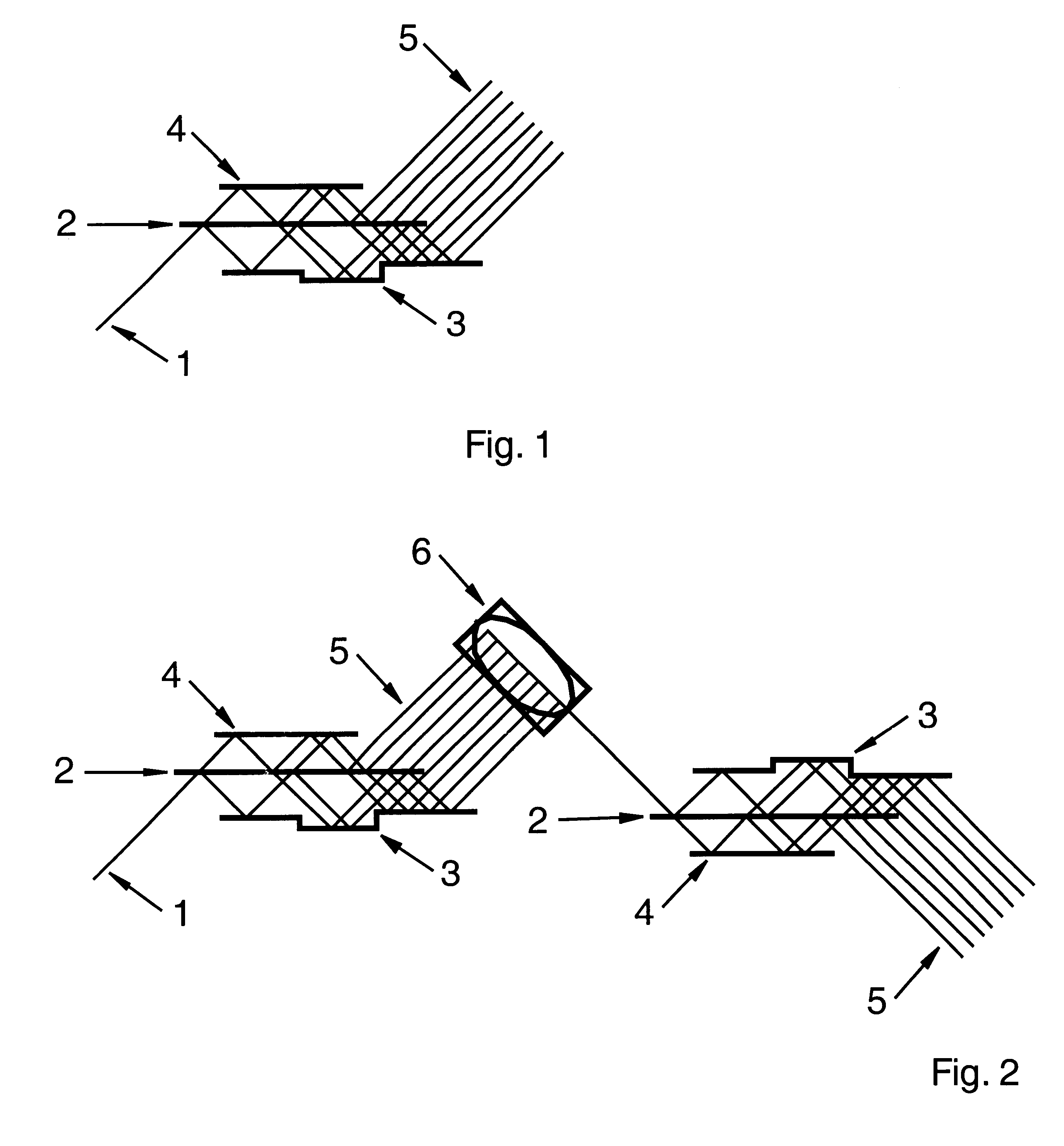
FIG. 1 shows a beam splitter constructed as an embodiment of the present invention generating 8 partial beams (5) from the incident beam (1). The partial beams (5) are located side by side on a line. The high reflectivity mirror (3) is furnished with a step, i.e. the distance of this mirror to the high reflectivity mirror (4) and to the partially reflecting mirror (2) respectively is variable through this step (3).

In the beam splitter according to FIG. 2 a periscope (6) is inserted between two optical arrangements splitting the laser beam. The partial beams (5) hit the periscope and are directed by the periscope towards the second optical arrangement to be split further. The second optical arrangement splits every partial beam into several partial beams (5) in such a way that a two-dimensional array of partial beams is generated. The same result can be achieved if both optical arrangements that split the laser beam are tilted with respect to each other in particular by an angle of 9...


PUM


Abstract

The method for splitting and reflecting beams in a laser scanning microscope which produces a laser beam (1) comprises the steps of: reflecting a beam from a partially reflecting mirror (2); splitting the laser beam (1) with a splitting device into partial beams (5); causing the partial beams to travel in a plane; directing the partial beams to a sample under investigation; providing the partially reflecting mirror (2) with a constant transmission; placing the partially reflecting mirror between two high reflectivity mirrors (3,4); transmitting the laser beam (1) to one of the high reflectivity mirrors (3); reflecting said beam (1) to the other one of the high reflectivity mirrors (4) with basically equal attenuation; repeatedly transmitting the beam to one of the mirrors; and repeatedly reflecting the beam to the other one of said mirrors (4); arranging the partially reflecting mirror and the high reflectivity mirrors (3,4) relative to each other to cause beams (5) reflected by the partially reflecting mirror (2) not to coincide with beams reflected by said high-reflectivity mirrors (3,4); shifting forwardly, at an exit region of the splitting device, an edge of the partially reflecting mirror (2) along an edge of one of the high-reflective mirrors (4); and shifting rearwardly an edge of the other high-reflective mirror (3).

Description

This application claims priority from German Application No. DE 199 04 592.5 filed Feb. 5, 19991. Field of the InventionThe present invention deals with a beam splitting device in particular for a laser scanning microscope, comprising a laser producing a laser beam and a system of intentionally arranged partially and totally reflecting mirrors splitting the laser beam into multiple partial beams, whereby the partial beams leave the beam splitter device in a plane and are fed to the sample under investigation.2. Description of the Prior ArtFrom the previous art (DE 196 53 413 A1) it is known that a multitude of partial beams can be produced by allowing an expanded laser beam to be incident on a micro-lens array.This means in particular, that each partial beam is generated from a different spatial part of the beam profile of the incident beam. The partial beams are focused by the micro lenses according to their focal length in one or more closely spaced planes behind the micro lens ar...

Claims


Application Information

Patent Timeline
Patent Type & Authority Patents(United States)
IPC IPC(8): G02B27/14G02B5/08G02B21/00G02B21/06
CPCG02B27/106G02B27/144G02B27/145
Inventor NIELSEN, TIMANDRESEN, PETER
Owner LAVISION
Why Eureka
Try Eureka