Method and device for the after-cooling of a preform in the injection molding process

a technology of injection molding and aftercooling, which is applied in the field of aftercooling of preforms in injection molding processes, can solve the problems of limited cooling performance in the after-cooling process, only insufficient cooling of preforms, and deterioration of plastic materials, so as to avoid unwelcome air vibrations

Inactive Publication Date: 2001-05-01
FARRAG RAINER
View PDF3 Cites 69 Cited by
  • Summary
  • Abstract
  • Description
  • Claims
  • Application Information

AI Technical Summary

Benefits of technology

In order to avoid these disadvantages, the invention in a further form of execution provides that the cooling blast station does not consist of a simple plunger tube, which is admitted into the preform, but that on the outlet of the preform there is now emplaced with sealing effect an exhaust air collecting chamber, and that the air escaping from the preform and loaded only with relatively slight absorbed heat is collected in the exhaust air collecting chamber, and is only then removed over an outlet.
The arrangement of an exhaust air collecting chamber has the advantage, therefore, that the cooling exhaust air escaping from the preform can be collected in the exhaust air collecting chamber and then, via one or several outlets, further used purposefully.
In the first place by the utilization of such an exhaust air collecting chamber which is emplaced with sealing effect on the after-cooling plate, undesired air vibrations

Problems solved by technology

With this after-cooling of the preform in the after-cooling plate there is present, however, the disadvantage that the preform is only insufficiently cooled, because precisely the cooling performance in this after-cooling process is limited.
As stated, the cooling occurs only on the outer circumference of the preform, which leads to the result that a temperature gradient arises in the direction of the interio

Method used


Image

  • Method and device for the after-cooling of a preform in the injection molding process
  • Method and device for the after-cooling of a preform in the injection molding process
  • Method and device for the after-cooling of a preform in the injection molding process

Examples


Embodiment Construction

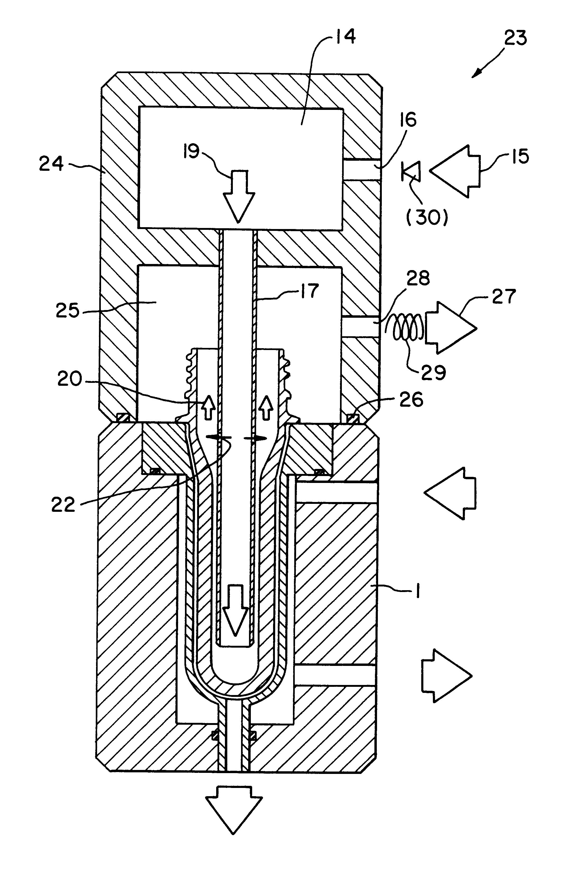
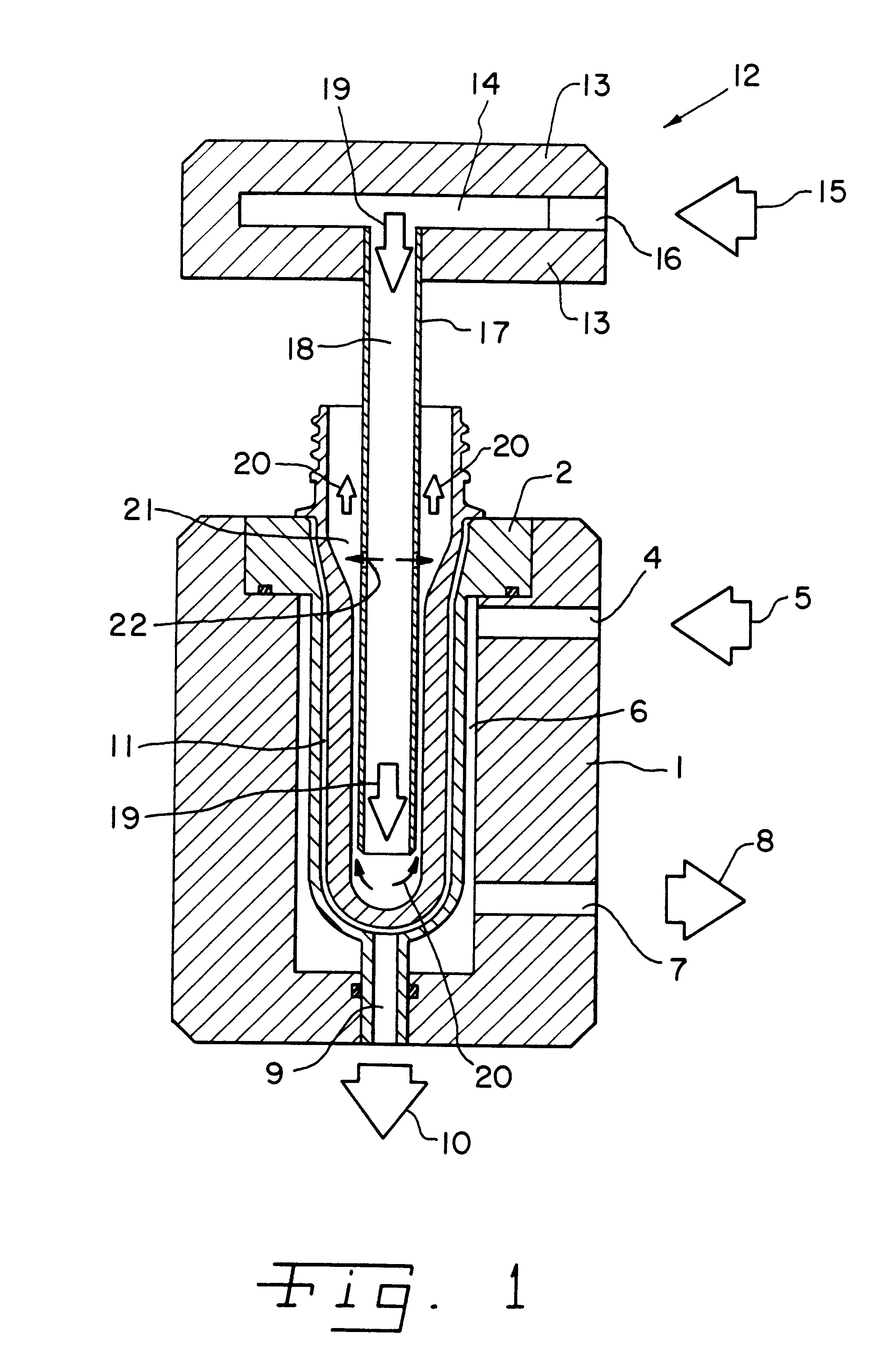
In FIG. 1 there is generally represented an after-cooling plate 1, which, in the interest of simplicity, is represented only in simple form of execution. It was already pointed out in the general specification part that in the drawing plane of FIG. 1, this after-cooling plate 1 is repeated in multiple execution; i.e., several after-cooling plates are represented and present in succession in the drawing plane of FIG. 1 and in each after-cooling plate 1 there is arranged a corresponding inset 2 for a preform 3 to be cooled.

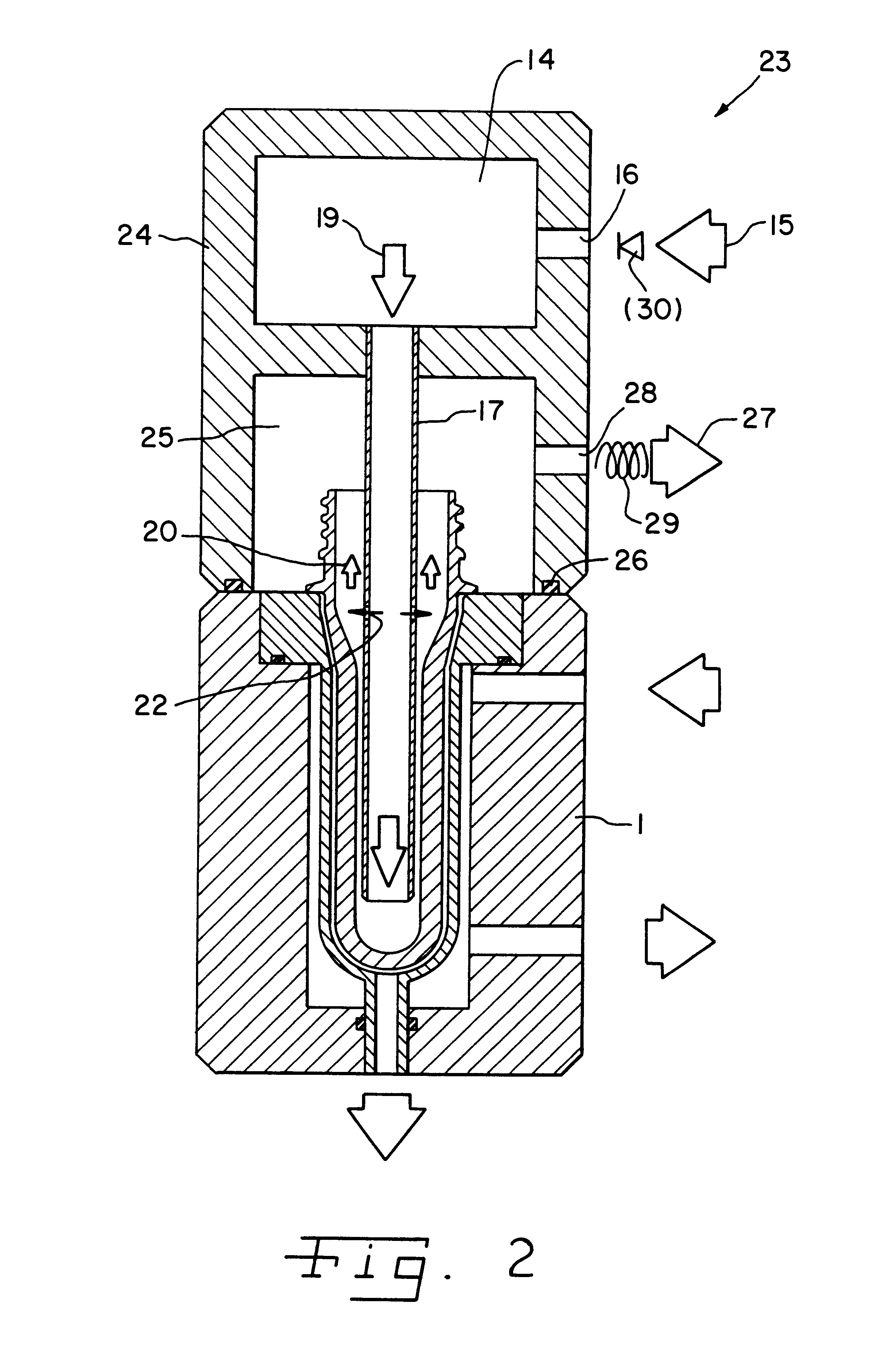
Obviously the after-cooling plates 1 can be arranged parallel next to one another in the drawing plane of FIG. 1 or of FIG. 2, so that they can be present adjacently to one another and also in succession with one another in multiple execution.

The same holds, furthermore, for the cooling blast station 12 represented according to FIG. 1, or the cooling blast station 23 according to FIG. 2, which in correspondence to the design of the after-cooling plate is present in ...


PUM

PropertyMeasurementUnit
Angleaaaaaaaaaa
Temperatureaaaaaaaaaa
Pressureaaaaaaaaaa

Abstract

The present invention relates to improving the after-cooling process of preforms from the injection molding process in respect to its efficiency and its economy.

Description

The object of the present invention is a method and a device for the after-cooling of a preform which was produced in the injection molding processSuch preforms are produced in the injection molding process with the aim of blowing from them--in a later process step of a subsequent hollow blast process--hollow body such as, for example, a plastic bottle, a plastic container or the like. In order, therefore, to produce such a preform in the injection molding process there is required in a manner known per se an injection molding machine which essentially consists of two mold halves movable with respect to one another, in which the one mold half which is connected to an extruder injects corresponding hot-fluid plastic material into the mold half, after which then the mold half is cooled and the preform is now present in the injection molding machine in the allocated mold core.In order properly to cool such a still very hot preform, it is a known practice to remove the preform from the ...

Claims


Application Information

Patent Timeline
IPC IPC(8): B29C35/00B29C35/16B29C45/72
CPCB29C35/16B29C45/7207B29C2035/165B29C2035/1658B29K2105/253B29C49/643
Inventor FARRAG, RAINER
Owner FARRAG RAINER
Why Eureka
Try Eureka