
Method and apparatus for preventing deposits from forming in a turbomolecular pump having magnetic or gas bearings

a technology of magnetic or gas bearings and turbomolecular pumps, which is applied in mechanical equipment, machines/engines, liquid fuel engines, etc., can solve problems such as damage to the rotor, rotors tend to form, and electrical discharge between the rotor and the stator

Inactive Publication Date: 2001-05-01
ALCATEL LUCENT SAS
View PDF9 Cites 30 Cited by
  • Summary
  • Abstract
  • Description
  • Claims
  • Application Information

AI Technical Summary

Benefits of technology

The problem that the present invention proposes to solve is that of preventing the formation of deposits that would disturb the electrical discharges inside a turbomolecular pump having magnetic or gas bearings and connected to an enclosure containing plasma, without significantly adversely affecting pumping speed or the industrial process inside the enclosure.

Problems solved by technology

While such turbomolecular pumps are being used in plasma deposition or etching processes, it has been observed that deposits tend to form of materials coming from the reaction products.
The pressure conditions in the high-pressure portion of the turbomolecular pump, combined with the short distance between the rotor and the stator and also with the potential difference between the rotor and the stator cause electrical discharges to occur between the rotor and the stator.
Unfortunately, when deposits form, they disturb the discharges by creating preferential paths, and zones are created in which arc conditions occur in which high current densities are set up, thereby rapidly damaging the rotor.
Unfortunately, the high density of the plasmas used requires very fine-mesh grids, sometimes of mesh size less than 100 .mu.m.
Under such conditions, the presence of grids reduces the conductance of the pump considerably, and significantly reduces its pumping speed.
In addition, such a very fine-mesh grid is a site on which deposits form that can then generate particles detrimental to the industrial process that is performed in the enclosure.
However, given the nature of the materials used and the high speed of rotation of the rotor, temperatures are rapidly reached that generate phenomena of material creep, thereby destroying the pump without even being effective in preventing deposits from forming.

Method used


Image

  • Method and apparatus for preventing deposits from forming in a turbomolecular pump having magnetic or gas bearings
  • Method and apparatus for preventing deposits from forming in a turbomolecular pump having magnetic or gas bearings

Examples


Embodiment Construction

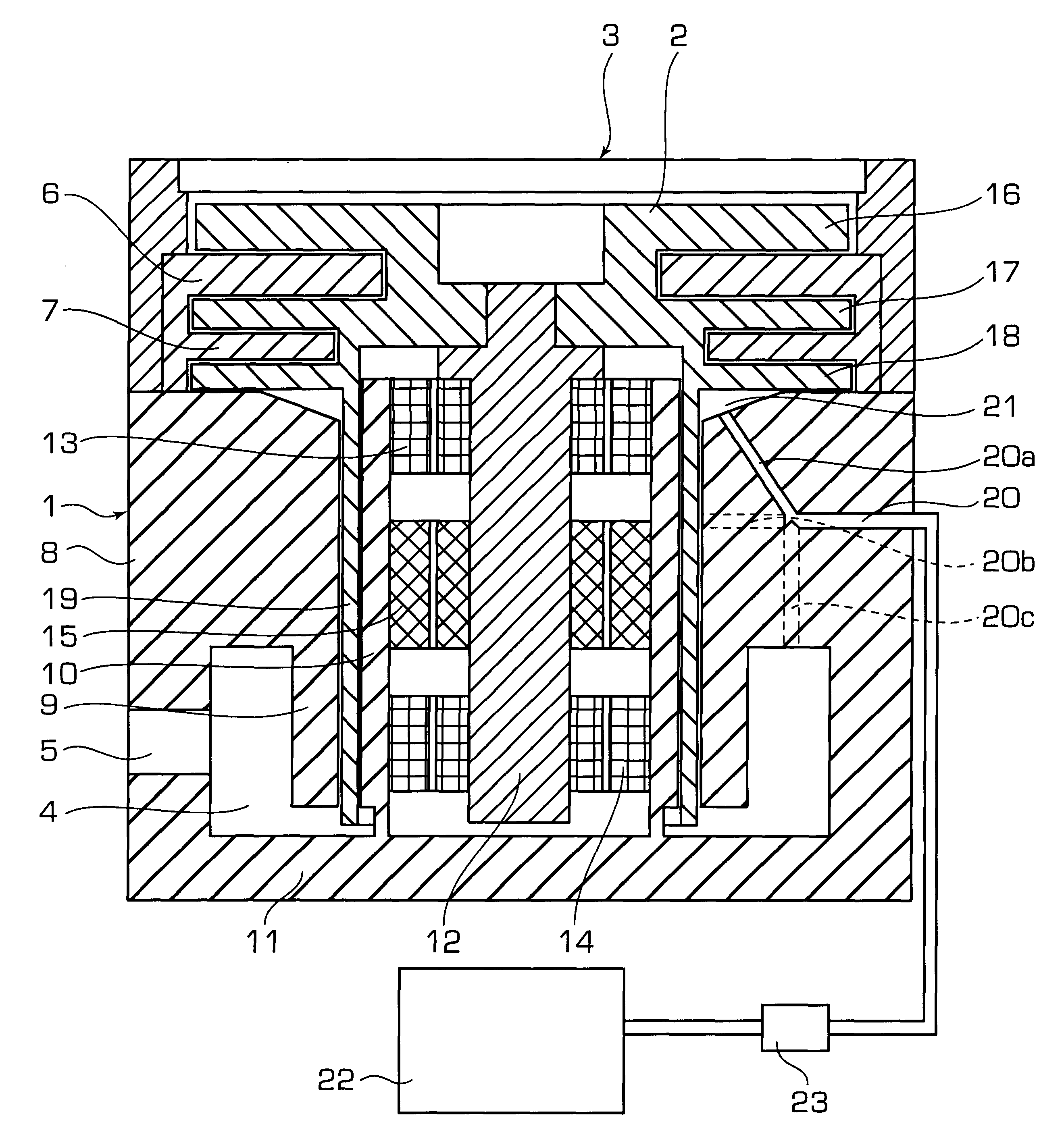
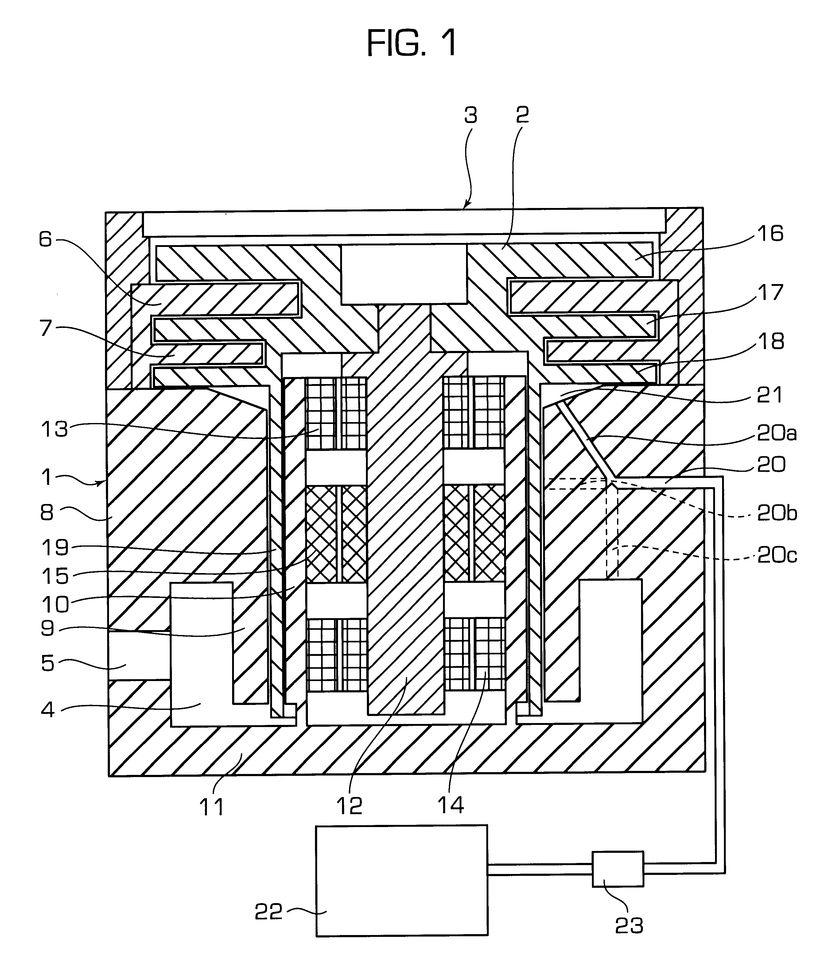
In the embodiment shown in FIG. 1, the turbomolecular pump of the invention comprises a conventional hybrid structure, with a stator 1 and a rotor 2 having a plurality of stages. The top of the stator 1 is open to form a suction inlet 3, and the stator is provided with an internal recess that is shaped to receive the rotor 2, with a bottom annular volume 4 for collecting the pumped gases and communicating with a bottom delivery outlet 5 on the side.

In the embodiment shown in the figure, and starting from the suction inlet 3, the stator 1 is provided with a plurality of stationary blade stages such as the stages 6 and 7, followed by a Holweck-type stator stage 8 with an outer tubular Holweck stator portion 9 and an inner tubular Holweck stator portion 10 that are coaxial and that are connected together via the bottom 11 so as to form between them an annular chimney communicating with the bottom annular volume 4.

The rotor 2 is secured to a shaft 12 carried by magnetic or gas bearings ...


PUM


Abstract

In the invention, deposits that disturb electrical discharges between the rotor and the stator inside a turbomolecular pump with a plurality of stages on magnetic or gas bearings are prevented from forming by injecting an active gas at at least one suitable location inside the pump via at least one gas intake pipe, which active gas reacts with the deposit-generating molecules and forms gaseous compounds that are removed by the pump. Such deposits are thus prevented from forming without disturbing the conductance of the pump or adversely affecting the atmosphere present in the enclosure to which the pump is connected.

Description

The present invention relates to turbomolecular pumps which, associated with primary pumps, make it possible to generate and sustain a hard vacuum in an enclosure.In general, a turbomolecular pump comprises a rotor and a stator having a plurality of stages, the rotor being carried by bearings. Going from the inside of the enclosure towards the outside, the gas pressure increases progressively from one stage to the next, and the stages close to the inside of the enclosure are considered to be low-pressure stages, while the stages close to the outlet are considered to be high-pressure stages.When it includes magnetic or gas bearings for supporting the rotor, such a turbomolecular pump has the characteristic that its rotor is isolated physically and therefore electrically from the stator and from the body of the pump which finds itself at reference potential, i.e. at the ground potential of the equipment.Turbomolecular pumps are frequently used in plasma deposition or etching equipment...

Claims


Application Information

Patent Timeline
Patent Type & Authority Patents(United States)
IPC IPC(8): F04D29/00F04D19/04F04D19/00F04D29/70
CPCF04D19/04F04D29/70F05D2260/607F04D29/701
Inventor PUECH, MICHEL
Owner ALCATEL LUCENT SAS
Learn More