
Method for processing and integrating copper interconnects

a technology of interconnects and copper, applied in the manufacture of cables/conductor components, solid-state devices, basic electric elements, etc., can solve the problems of reducing yield and reliability, degrading interconnect performance and noise margins, and increasing complexity of integrated circuits

Inactive Publication Date: 2001-05-01
TAIWAN SEMICON MFG CO LTD
View PDF10 Cites 13 Cited by
  • Summary
  • Abstract
  • Description
  • Claims
  • Application Information

AI Technical Summary

Benefits of technology

It is yet another object of the present invention to provide a producible and economical method for forming copper interconnects and lines in tenches in a dielectic layer using a self-aligned copper electroplating process.
The present invention provides considerable improvement over the prior art. Because no copper chemical-mechanical polishing is required, the risk of copper migration and reduced dielectric strength and / or shorting is reduced. The method of the present invention can be economically performed using existing semiconductor processing equipment and technology.

Problems solved by technology

Integrated circuits continue to increase in complexity each year.
However, microminiturization reduces yield and reliability, and degrades interconnect performance and noise margins.
However, its use has presented many manufacturing problems, such as the possibility of diffusion into the semiconductor substrate, the low adhesive strength of copper to various dielectric materials, and the difficulty in planarizing a copper layer without erosion or dishing occuring which reduces the performance and impedes the ability to stack multiple layers.
However, this patent does not disclose or suggest planarizing the copper structures.
The inventors have identified a problem in a process known to them for forming copper interconnects for a semiconductor device using a dual-damascene process.
The problem identified by the inventors is that chemically-mechanically polishing copper (Cu CMP) can cause diffusion of the copper, resulting in contamination and reduced dielectric strength.
However, the copper used to form the metal interconnects diffuses during the CMP process, resulting in contamination and a reduced dielectric strength.

Method used


Image

  • Method for processing and integrating copper interconnects
  • Method for processing and integrating copper interconnects
  • Method for processing and integrating copper interconnects

Examples


Embodiment Construction

--FIGS. 7 through 13

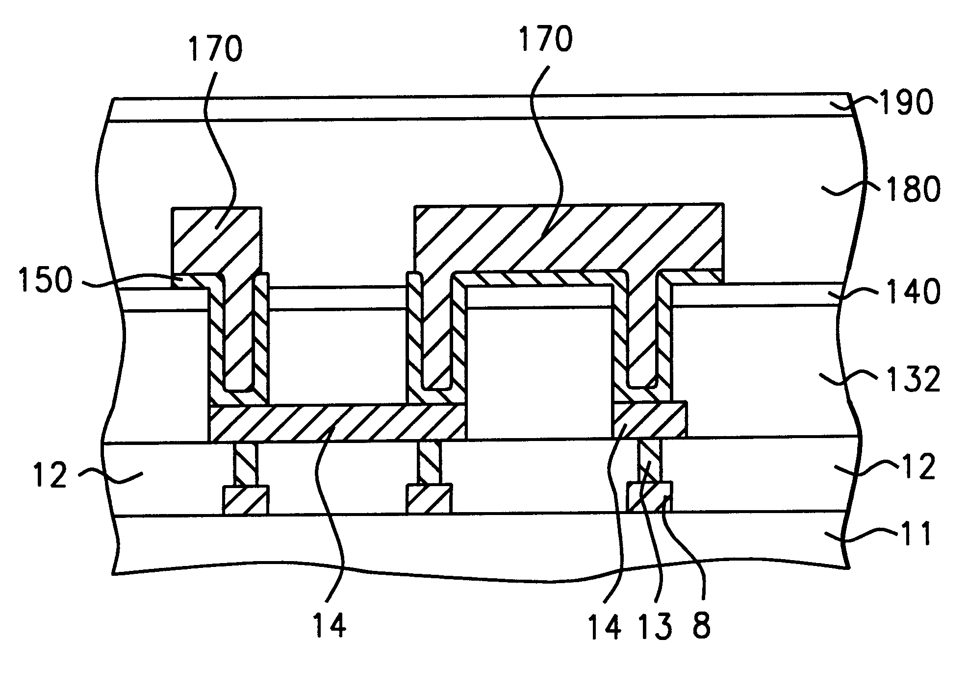
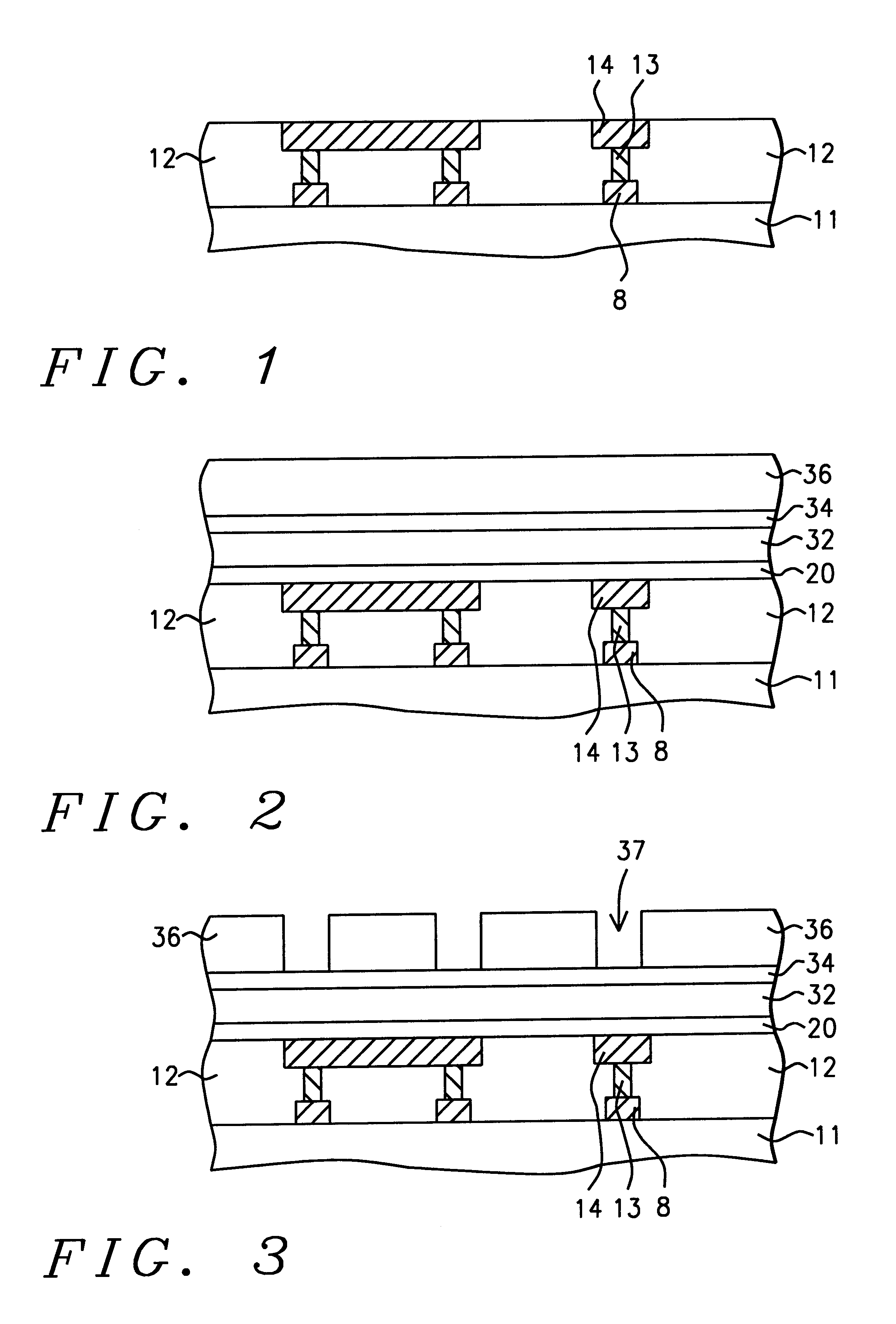
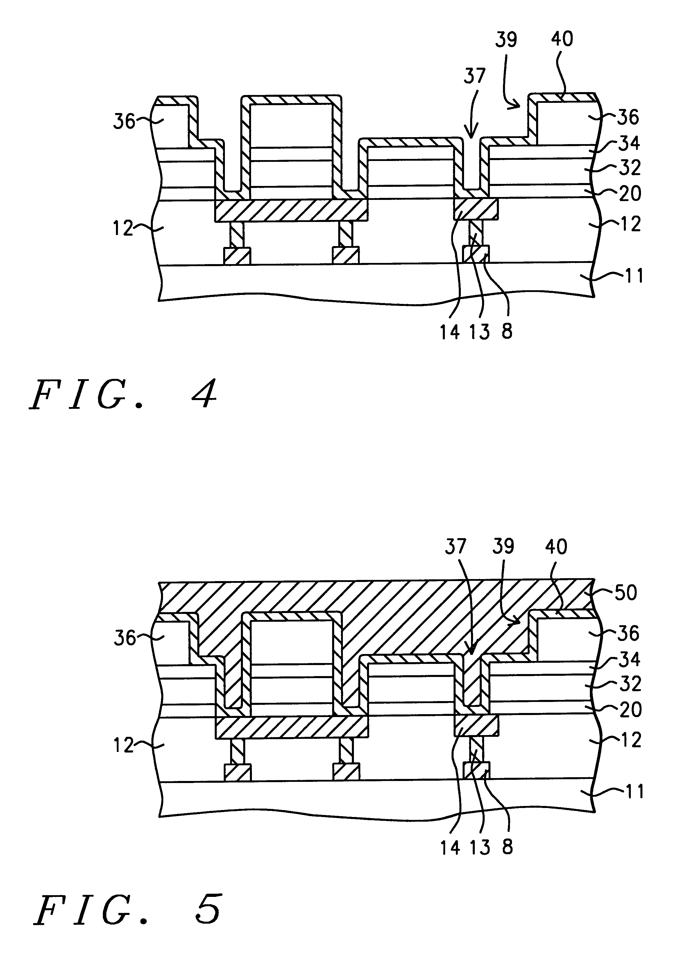
Referring to FIG. 7, the preferred embodiment of the present invention begins by providing a semiconductor structure (11) having a first metal layer (14) thereover. The first metal layer (14) can be in the form of metal lines deposited in trenches in a dielectric layer (12), wherein conductive plugs (13) connect the first metal layer (14) to devices (8) on the semiconductor substrate (11).

Semiconductor structure (11) is understood to possibly include a substrate comsisting of a semiconducting material such as monocrystalline silicon or germanium or a silicon on insulator (SOI) structure as is known in the art. Semiconductor structure (11) is understood to possibly further include conductive layers and / or insulating layers formed over a substrate or the like, and passive and or active devices formed over and / or in the substrate or the like.

Still referring to FIG. 7, in the preferred embodiment of the present invention, a first inter-metal dielectric layer (132) is...


PUM

PropertyMeasurementUnit
thicknessaaaaaaaaaa
thicknessaaaaaaaaaa
thicknessaaaaaaaaaa

Abstract

A method for forming copper interconnects, without inducing copper diffusion, by eliminating the copper chemical-mechanical polishing process. A semiconductor structure is provided having a first metal layer thereover. A first inter-metal dielectric layer is formed over the first metal layer and planarized. A first resist layer is formed over the first inter-metal dielectric layer, and the first resist layer and the first inter-metal dielectric layer are patterned to form via openings with the first metal layer forming the bottoms of the via openings. A barrier / seed layer, comprising a barrier layer and an overlying seed layer, is formed on the sidewalls and bottoms of the via openings. A self-align layer, composed of a high-resistivity, inorganic material, is formed over the barrier / seed layer. The self-align layer is patterned to reform the via openings and to form trench openings, exposing the barrier / seed layer on the bottoms and sidewalls of the via openings and on the bottoms of the trench openings. A copper layer is electroplated onto the exposed barrier / seed layer at the bottoms and sidewalls of the via openings and on the bottom of the trenches. The remaining portions of the self-align layer removed, then the exposed portions of the barrier / seed layer are removed.

Description

BACKGROUND OF INVENTION1. Field of the InventionThis invention relates generally to fabrication of a semiconductor device and more particularly to a method for forming a copper structure, such as interconnections without performing a copper chemical-mechanical polishing (CMP) step, reducing the risk of copper contamination.2. Description of the Prior ArtIntegrated circuits continue to increase in complexity each year. As applications develop for memories, microprocessors, and minicomputers there is an increasing demand for greater microminiturization, greater switching speeds, and smaller and less costly integrated circuit semiconductor devices.Increased device microminiturization improves device performance and packing density while reducing cost per unit. However, microminiturization reduces yield and reliability, and degrades interconnect performance and noise margins.Continued microminiturization of semiconductor devices using non-scaling aluminum lines would require the use of ...

Claims


Application Information

Patent Timeline
Patent Type & Authority Patents(United States)
IPC IPC(8): H01L21/768H01L21/70H01L23/532H01L23/52
CPCH01L21/76843H01L21/76873H01L21/76879H01L21/76885H01L23/53238H01L2924/0002H01L2924/00
Inventor LEE, FU-SHENGCHEN, CHIEN-CHENLIN, CHEN-TINGLU, CHEH-CHIEH
Owner TAIWAN SEMICON MFG CO LTD
Learn More