Dual plasma source for plasma process chamber

a plasma process chamber and plasma source technology, applied in gas-filled discharge tubes, electric discharge lamps, solid cathodes, etc., can solve the problems of quartz plasma tube degradation, less efficient material use for constructing plasma tubes,

Inactive Publication Date: 2001-05-01
LAM RES CORP
View PDF8 Cites 330 Cited by
  • Summary
  • Abstract
  • Description
  • Claims
  • Application Information

AI Technical Summary

Benefits of technology

A dual plasma source is provided for a plasma processing system, comprising a first plasma source and a second plasma source. The first plasma source has a first plasma passageway for transporting a first plasma therethrough toward a processing chamber, the first plasma passageway providing a first inlet for accepting a first gas mixture to be energized by the first plasma source. The second plasma source is connected to the first plasma source and has a second plasma passageway for transporting a second plasma therethrough toward the processing chamber, the second plasma passageway providing a second inlet for accepting a second gas mixture to be energized by the second plasma source. The first plasma passageway is constructed from a material that retards atomic oxygen recombination in the first plasma, and the second plasma passageway is constructed from a material that resists etching by the second plasma. In a more limited embodiment, the first plasma passageway is constructed from quartz (SiO.sub.2) and the second plasma passageway is constructed from alumina (Al.sub.2 O.sub.3) or single crystal alumina (sapphire).

Problems solved by technology

Other types of materials used for constructing the plasma tube are less efficient in transporting the plasma to the process chamber.
Such improved ash rates (and residue removal capabilities of fluorine), however, are achieved at the expense of degradation of the quartz plasma tube.
However, the use of a sapphire tube for such a plasma reintroduces the problem of atomic oxygen recombination with the inner surface of the sapphire tube.

Method used


Image

  • Dual plasma source for plasma process chamber
  • Dual plasma source for plasma process chamber
  • Dual plasma source for plasma process chamber

Examples


first embodiment

The second plasma source 84a is a radio frequency (RF) driven plasma source comprising an RF source 102a (second power source) and a coil 104a (second power transfer mechanism) through which the second plasma tube 88a passes. A desired mixture of gases (e.g., a fluorinated gas such as carbon tetrafluoride) is optionally introduced into the second plasma tube 88a via second inlet 92a. A switch (not shown) may be used to establish or cut off the flow of a fluorinated gas to second inlet 92a. RF energy generated by the RF source 102a (e.g., operating at 13.56 MHz) and coupled to the coil 104a energizes the gas mixture located in the portion of the second plasma tube 88a surrounded by the coil. In this first embodiment of FIG. 2, the second plasma tube is constructed of a material that resists etching by the fluorine-containing second plasma, such as alumina (Al.sub.2 O.sub.3) or single crystal alumina (sapphire). Altematively, the second power source may be constructed of Al.sub.2 N.su...

fifth embodiment

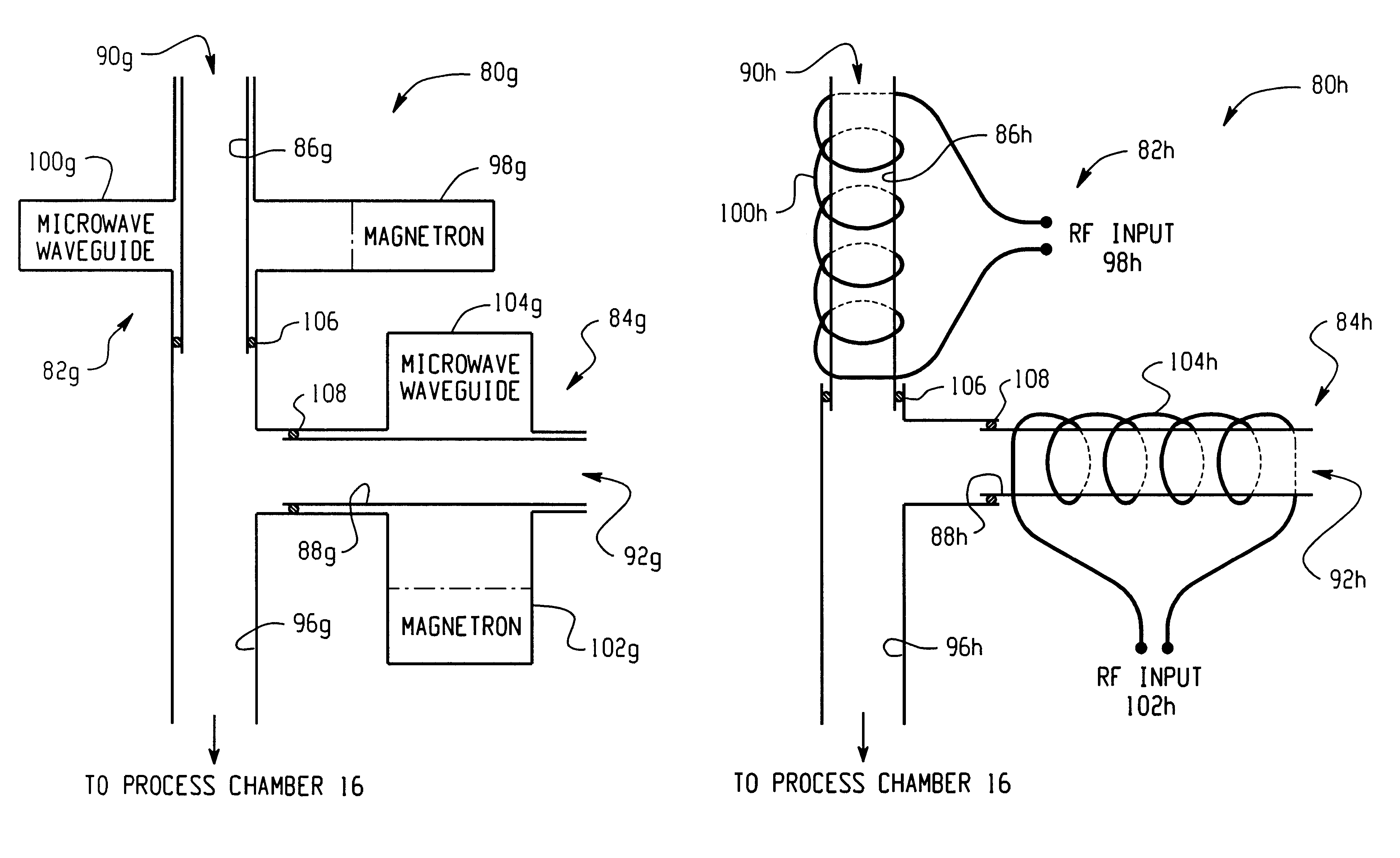
Referring to FIG. 6, a dual plasma source 80e is shown. The first plasma source 82e is a microwave driven plasma source comprising a magnetron 98e (first power source) and a waveguide 100e (first power transfer mechanism) through which the first plasma tube 86e passes. A desired mixture of oxygen-containing or fluorine-containing gases is introduced into the first plasma tube 86e via first inlet 90e. Microwave energy generated by the magnetron 98e (e.g., operating at 2.45 GHz) and coupled to the waveguide 100e energizes the gas mixture located in the portion of the first plasma tube 86e surrounded by the waveguide.

The second plasma source 84e is a radio frequency (RF) driven plasma source comprising an RF source 102e (second power source) and a coil 104e (second power transfer mechanism) through which the second plasma tube 88e passes. A desired mixture of fluorine-containing or oxygen-containing gases is introduced into the second plasma tube 88e via second inlet 92e. RF energy gen...


PUM

PropertyMeasurementUnit
energyaaaaaaaaaa
power transferaaaaaaaaaa
poweraaaaaaaaaa

Abstract

A dual plasma source (80) is provided for a plasma processing system (10), comprising a first plasma source (82) and a second plasma source (84). The first plasma source (82) has a first plasma passageway (86) for transporting a first plasma therethrough toward a processing chamber (16), the first plasma passageway providing a first inlet (90) for accepting a first gas mixture to be energized by the first plasma source. The second plasma source (84) is connected to the first plasma source (82) and has a second plasma passageway (88) for transporting a second plasma therethrough toward the processing chamber (16), the second plasma passageway providing a second inlet (92) for accepting a second gas mixture to be energized by the second plasma source. The first plasma passageway (86) is constructed from a material that resists atomic oxygen recombination with the first plasma, and the second plasma passageway (88) is constructed from a material that resists etching by the second plasma. In a more limited embodiment, the first plasma passageway (86) is constructed from quartz (SiO.sub.2) and the second plasma passageway is (88) constructed from alumina (Al.sub.2 O.sub.3) or single crystal alumina (sapphire).

Description

FIELD OF THE INVENTIONThe present invention relates generally to the field of semiconductor processing systems such as photoresist ashers, and more specifically to a dual plasma source for use in such systems.BACKGROUND OF THE INVENTIONIn the manufacture of integrated circuits, photolithography techniques are used to form integrated circuit patterns on a substrate. Typically, the substrate is coated with a photoresist, portions of which are exposed to ultraviolet (UV) radiation through a mask to image a desired circuit pattern on the photoresist. The portions of the photoresist left unexposed to the UV radiation are removed by a processing solution, leaving only the exposed portions on the substrate. These remaining exposed portions are baked during a photostabilization process to enable the photoresist to withstand subsequent processing.After such processing, in which the integrated circuit components are formed, it is generally necessary to remove the baked photoresist from the wa...

Claims


Application Information

Patent Timeline
Patent Type & Authority Patents(United States)
IPC IPC(8): H01J37/32
CPCH01J37/32192H01J37/32357H01J37/32477
Inventor SRIVASTAVA, ASEEM K.
Owner LAM RES CORP
Why Eureka
Try Eureka