

Magnetic-head supporting mechanism
a support mechanism and magnetic head technology, applied in the direction of maintaining the head carrier alignment, recording information storage, instruments, etc., can solve the problems of significant differences in damage degree, and achieve the effect of improving impact resistance and reducing contact damag
- Summary
- Abstract
- Description
- Claims
- Application Information
AI Technical Summary
Benefits of technology
Problems solved by technology
Method used
Image

Examples
first embodiment
this invention is described with reference to FIGS. 1 to 9.
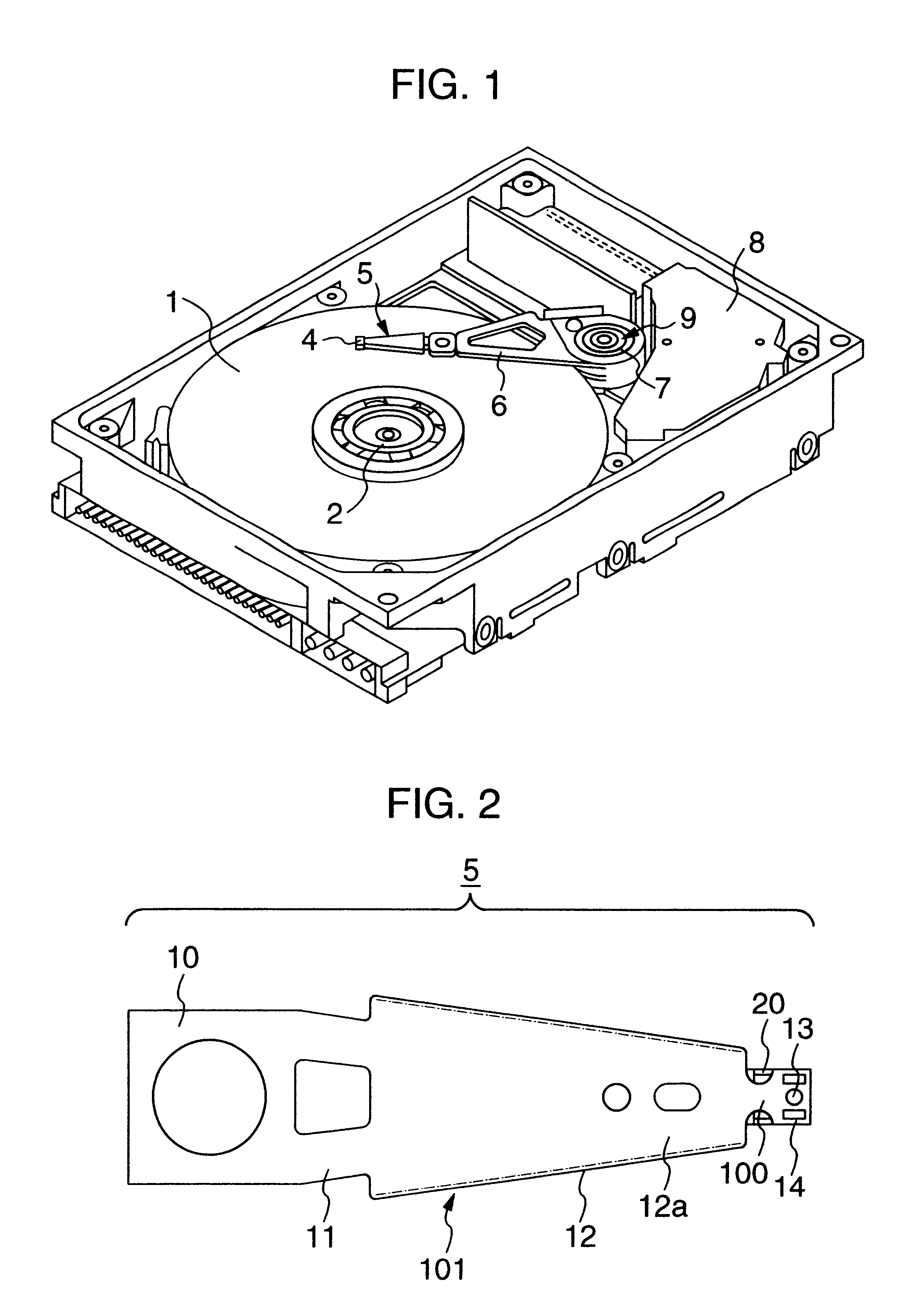
FIG. 1 shows a general view of a magnetic-disc apparatus in which a magnetic-head supporting mechanism according to a first embodiment of this invention is mounted.
A magnetic discs 1 on which information is recorded is laminated on a spindle 2. A magnetic head (not shown) used to record and reproduce information on and from the magnetic disc is mounted on a slider 4 of a magnetic-head supporting mechanism 5. The magnetic-head supporting mechanism 5 is joined with the arm 6. The magnetic head is placed at a predetermined radial position by a carriage 9 consisting of a pivot bearing 7 and a voice coil motor 8. These mechanisms are mounted in a lunch-box-shaped base and are sealed by a cover (not shown). The present magnetic-head supporting mechanism improves impact resistance to enable recording and reproduction at a high density even when the magnetic-disc apparatus is configured as a portable type.
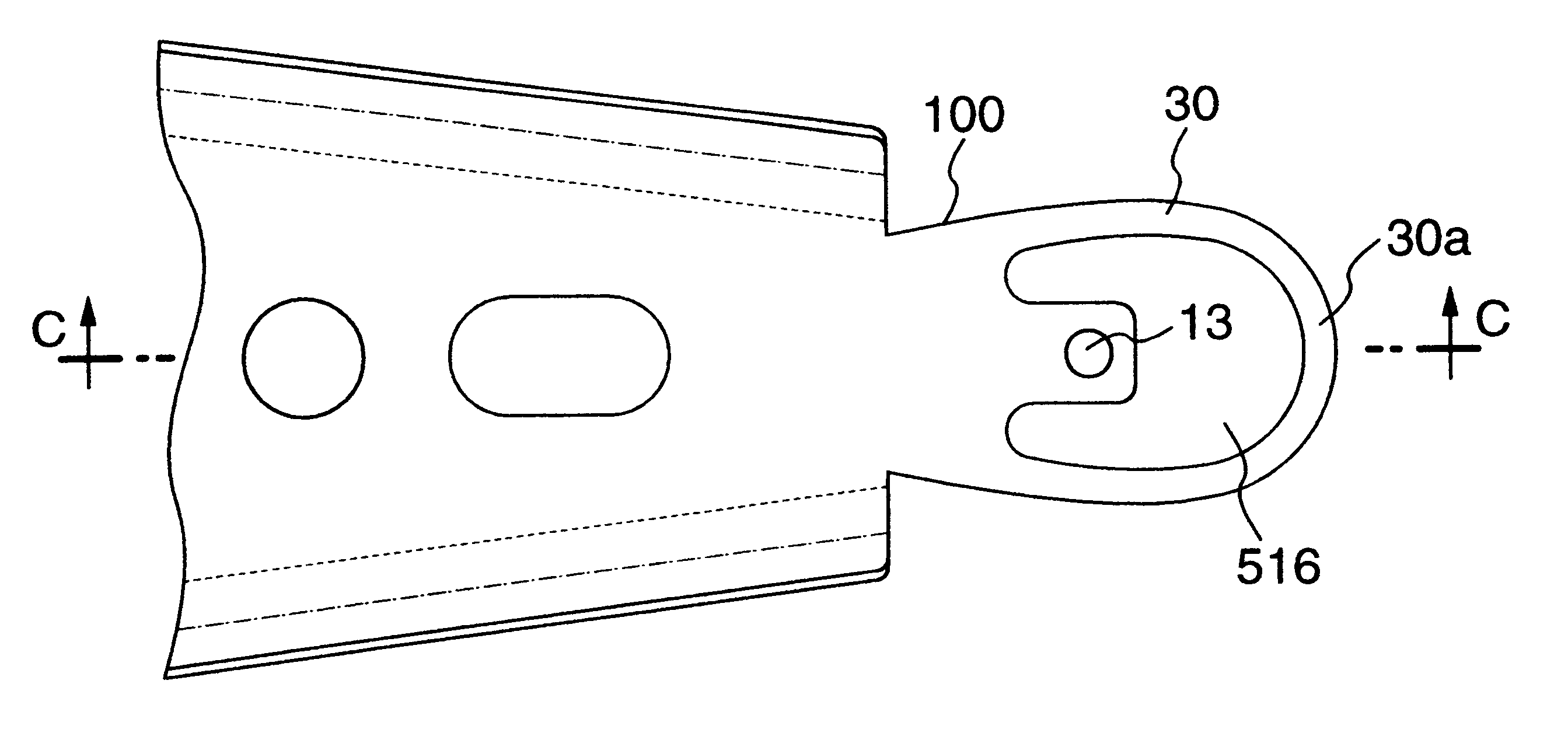
FIG. 2 shows the overall ma...
second embodiment
this invention is described with reference to FIGS. 10A and 10B. This figure shows only the roof portion of this embodiment in detail. The other sites are the same as in the first embodiment, so they are omitted. The second embodiment differs from the first embodiment in that it has a rotation angle adjustment groove 40 in the roof portion.
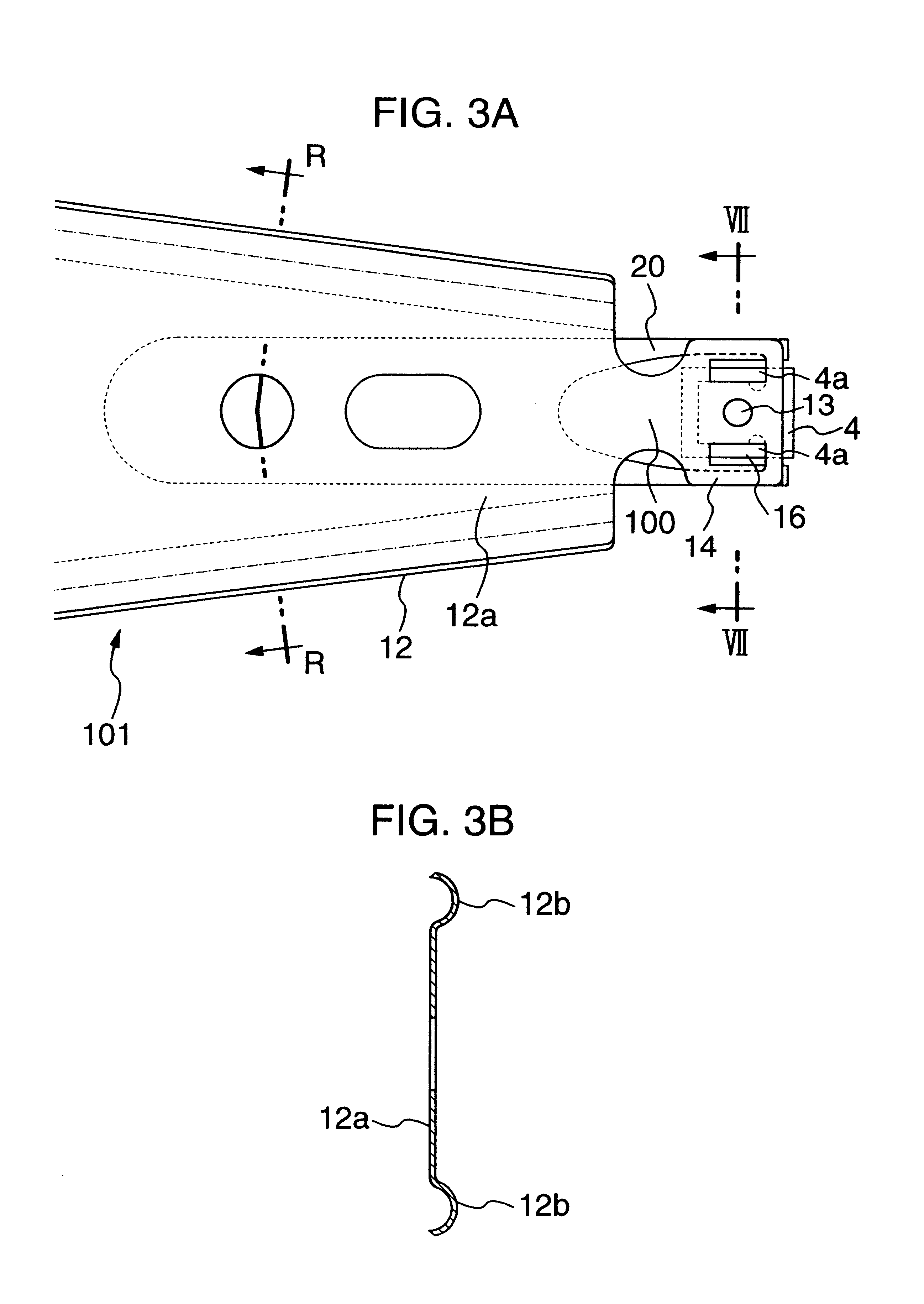
This groove is provided on the flexible finger portion of the gimbal to adjust the gap between the flexible finger portion and the roof. Specifically, according to the first embodiment, the gap between the flexible finger portion 22 and the roof 14 is 0.045 mm and the maximum rotation angle is 3.2.degree., as shown in FIG. 7A. This gap can be controlled to adjust the contact angle.
According to the first embodiment, the height of the pivot is used to control the gap. On the other hand, since the pivot is molded by press working, its height and accuracy are limited. The second embodiment includes a staged roof 17 having the rotating angle adjustment...
third embodiment
this invention is described with reference to FIG. 11. This embodiment differs from the second embodiment in that the rotation angle adjustment groove 40 is staged by means of press working. Thus, the height of the staged roof is different from that of the windows as shown in FIG. 11. On the other hand, the rotation angle adjustment groove 40 is provided in the top surface of the flexible finger portion of the gimbal via a predetermined gap as in the second embodiment. The staged roof with the rotation angle adjustment groove 40 improves the degree of freedom in design for the height of the pivot, thickness of the gimbal, and the thickness and length of the load beam, as in the second embodiment. In addition, since the staged roof can be press-worked simultaneously with the pivot 13, this embodiment provide better productivity (mass productivity) than the second embodiment. This embodiment also provides high impact resistance and mass productivity as in the first embodiment.
PUM
 Abstract
Description
Claims
Application Information