Optical coupler and illumination system employing the same

a technology of optical couplers and illumination systems, applied in the direction of optical light guides, bundled fibre light guides, instruments, etc., can solve the problems of inability to achieve widespread use, the area of closely spaced surfaces which will be illuminated by light emitted from light pipes is far too small to permi

Inactive Publication Date: 2001-05-01
WHELEN ENGINEERING COMPANY
View PDF25 Cites 54 Cited by
  • Summary
  • Abstract
  • Description
  • Claims
  • Application Information

AI Technical Summary

Problems solved by technology

However, despite the significant potential benefits offered by light head assemblies designed for use with optical waveguides and remotely located light sources, such assemblies have not found widespread utility due to a number of inherent deficiencies.
A major deficiency, as noted above, arises from the fact that a light pipe defines a very small area light source and the intensity of that source decreases rapidly off-axis.
Thus, the area of a closely spaced surface which will be illuminated by light emitted from a light pipe is far too small to permit, for example, the light pipe to function as a spot or warning light.
Previous attempts to control the dispersion of light emanating from a light pipe have resulted in light head assemblies with serious limitations.
A first limitation, as mentioned above, is imposed by the need to employ relatively complex lenses to refract the light emitted from the end of the light pipe.
In addition to being expensive, the use of such a lens results in a comparatively high degree of attenuation of the available light.
A second limitation of previously available light head assemblies which receive light via an associated light pipe resides in their elongated shape, i.e., their depth in the direction of travel of the light rays.
While such spacing improves light dispersion, it also results in a volumetrically inefficient device.
Light head assemblies employing such elongated housings are impractical for flush mounting on walls

Method used


Image

  • Optical coupler and illumination system employing the same
  • Optical coupler and illumination system employing the same
  • Optical coupler and illumination system employing the same

Examples


Embodiment Construction

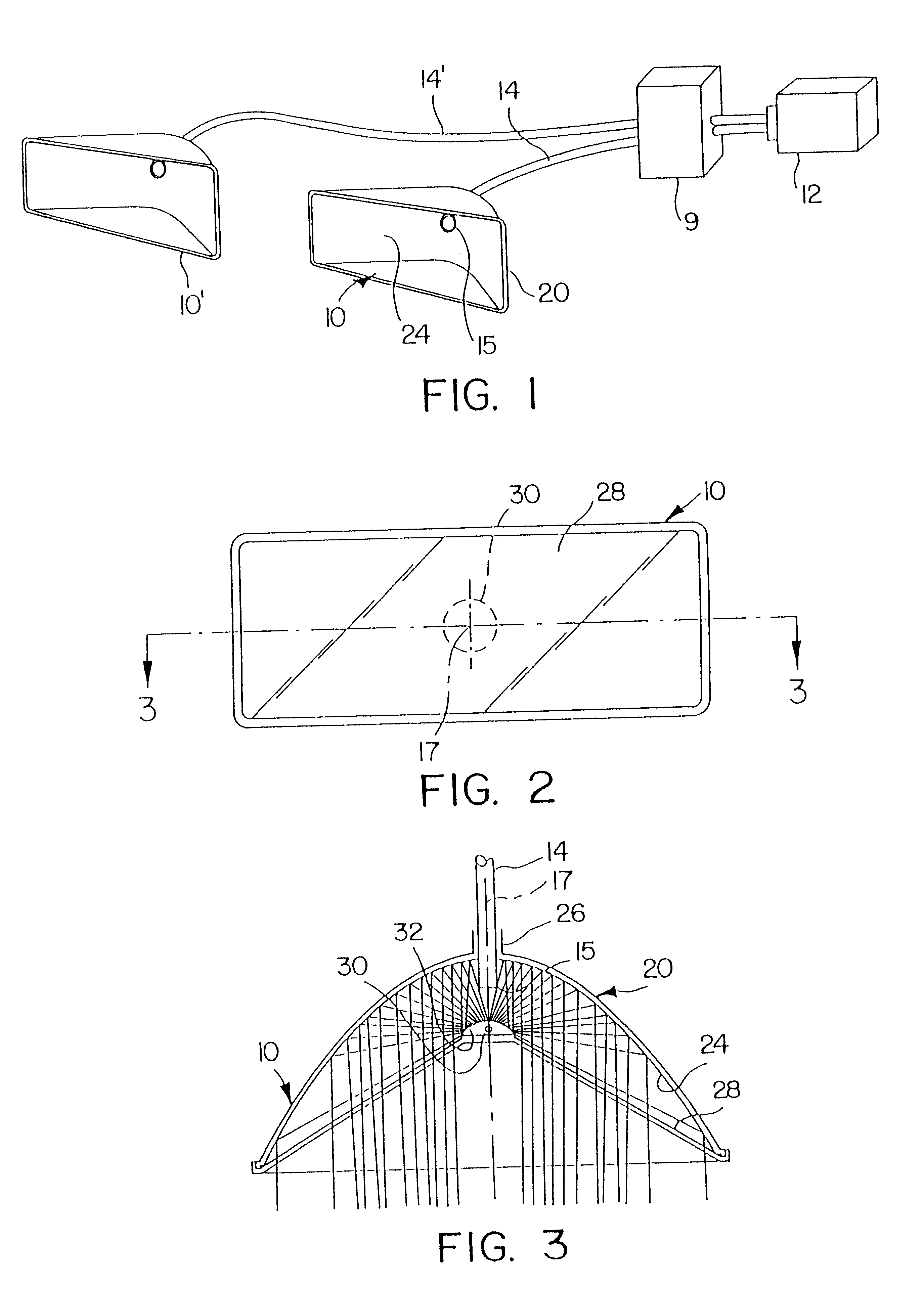
FIG. 1 schematically illustrates an illumination system in accordance with the present invention, this system including a pair of projection devices 10 and 10', i.e., a pair of light heads. Referring jointly to FIGS. 1-3, a first embodiment of a light head assembly 10 includes at least an optic deflector 30, a main reflector 20, a support 28 for deflector 30, and means 26 for receiving a light pipe 14. Reflector 20 generally serves as the light head housing and has a reflective surface 24 on one side thereof. In the embodiment of FIGS. 1-3, deflector 30 is in the form of a convex reflector and reflective surface 24 of reflector 20 is concave and symmetric about an axis 17. The light pipe receiving means 26 is integrally formed with reflector 20 such that the discharge end 15 of light pipe 14 is oriented coaxial to axis 17 when light pipe 14 is secured within light pipe receiving means 26.

Support positions 28 deflector 30 at an appropriate distance from, and with an appropriate orien...


PUM


Abstract

An illumination technique and system employing an optical waveguide to transmit light from a source, typically a light emitter which operates at high temperature, to a light head which creates a desired light dispersion pattern. The light head includes a member which emulates the light source and the emitted light is coupled from the source into the optical waveguide by a compact and efficient columnator comprising a pair of dissimilar three dimensional reflectors and a lens.

Description

1. Field of the InventionThe present invention relates to the creation of a desired light dispersion pattern using light transmitted via an optical waveguide from a remotely located source to a projection device. More particularly, the present invention relates to the use of a high intensity, high temperature light generator to provide light energy to a remotely located light head and, especially, to the coupling of light generated by such a source into one or more optical fibers for transmission to the light head. Accordingly, the general objects of the present invention are to provide novel and improved methods and apparatus of such character.2. Description of the Related ArtAttempts to illuminate an area using light generated by a remotely located light source and transmitted to a light head assembly or other luminaire via light guides are known in the art. To date, most light head assemblies designed for use with remote light sources have been mere variations on a single basic d...

Claims


Application Information

Patent Timeline
IPC IPC(8): F21V8/00
CPCG02B6/0008
Inventor LYONS, HAROLD W.
Owner WHELEN ENGINEERING COMPANY
Why Eureka
Try Eureka