Supercharge Your Innovation With Domain-Expert AI Agents!

Bypass air volume control device for combustor used in gas turbine

a technology of air volume control and gas turbine, which is applied in the direction of machines/engines, mechanical equipment, light and heating equipment, etc., can solve the problems of accelerated abrasion of the valve body, the shaft and the bearings, and the valve body in the channel to stutter

Inactive Publication Date: 2001-05-08
MITSUBISHI HITACHIPOWER SYST LTD
View PDF6 Cites 39 Cited by
  • Summary
  • Abstract
  • Description
  • Claims
  • Application Information

AI Technical Summary

Benefits of technology

With the invention described above, vibration due to combustion in a combustion chamber will not translate into vibration of structural components of a control valve. Combustion vibration will not result in self-induced vibration, and the abrasion of components which experience friction will be mitigated. The opening and closing of the bypass can be controlled reliably and stably.Furthermore, with this invention, any thermal expansion or assembly error experienced by connectors such as the links between the control valve in the bypass channel and the valve adjustment mechanisms on the outer surface of the casing can easily be absorbed.Other effects may also be achieved.

Problems solved by technology

When this happened, the resonant vibration of the pipe would cause the valve body in the channel to stutter.
This would result in greatly accelerated abrasion of the valve body, the shaft and the bearings for the valve stem in the bypass channel.

Method used


Image

  • Bypass air volume control device for combustor used in gas turbine
  • Bypass air volume control device for combustor used in gas turbine
  • Bypass air volume control device for combustor used in gas turbine

Examples


Embodiment Construction

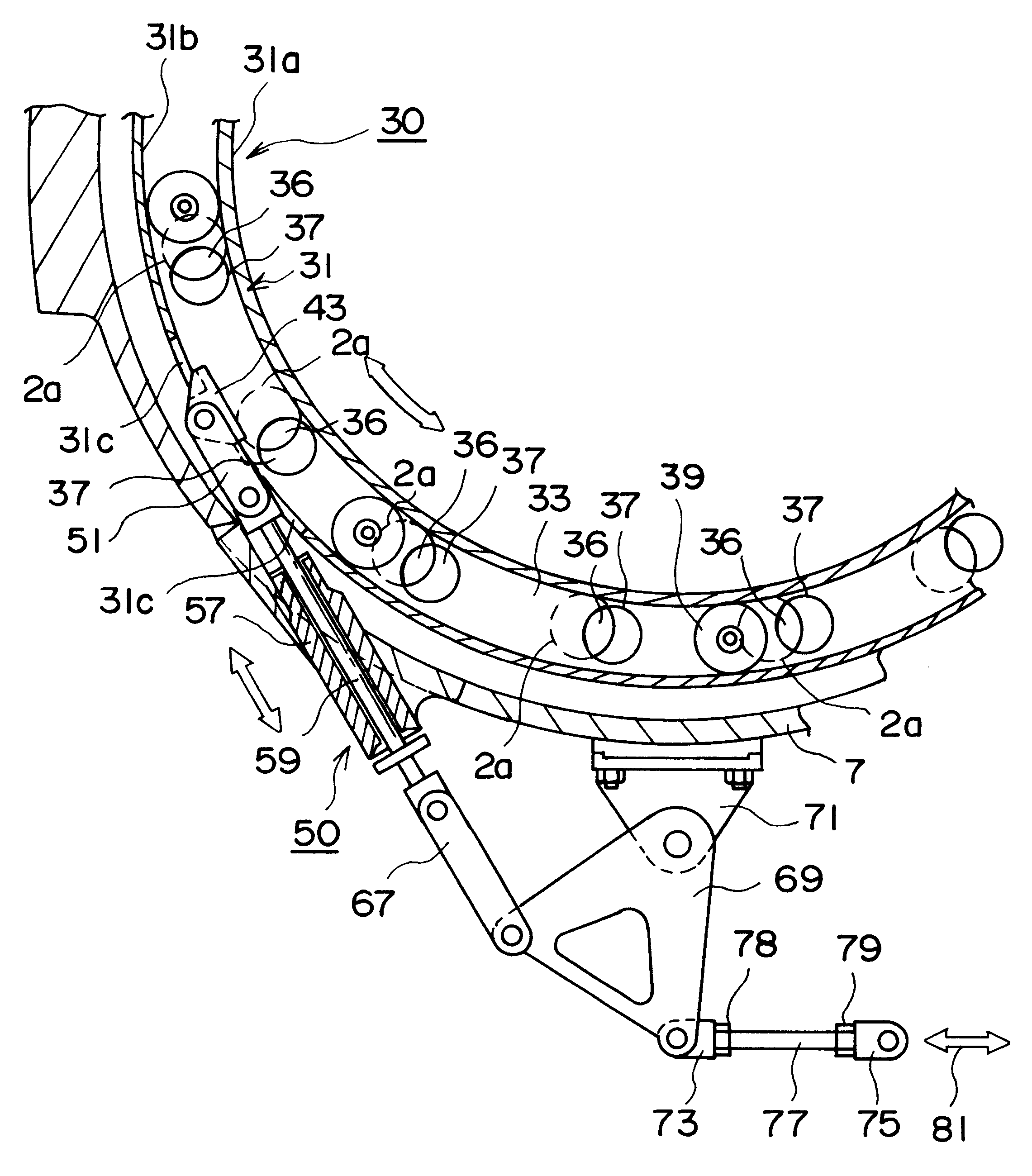
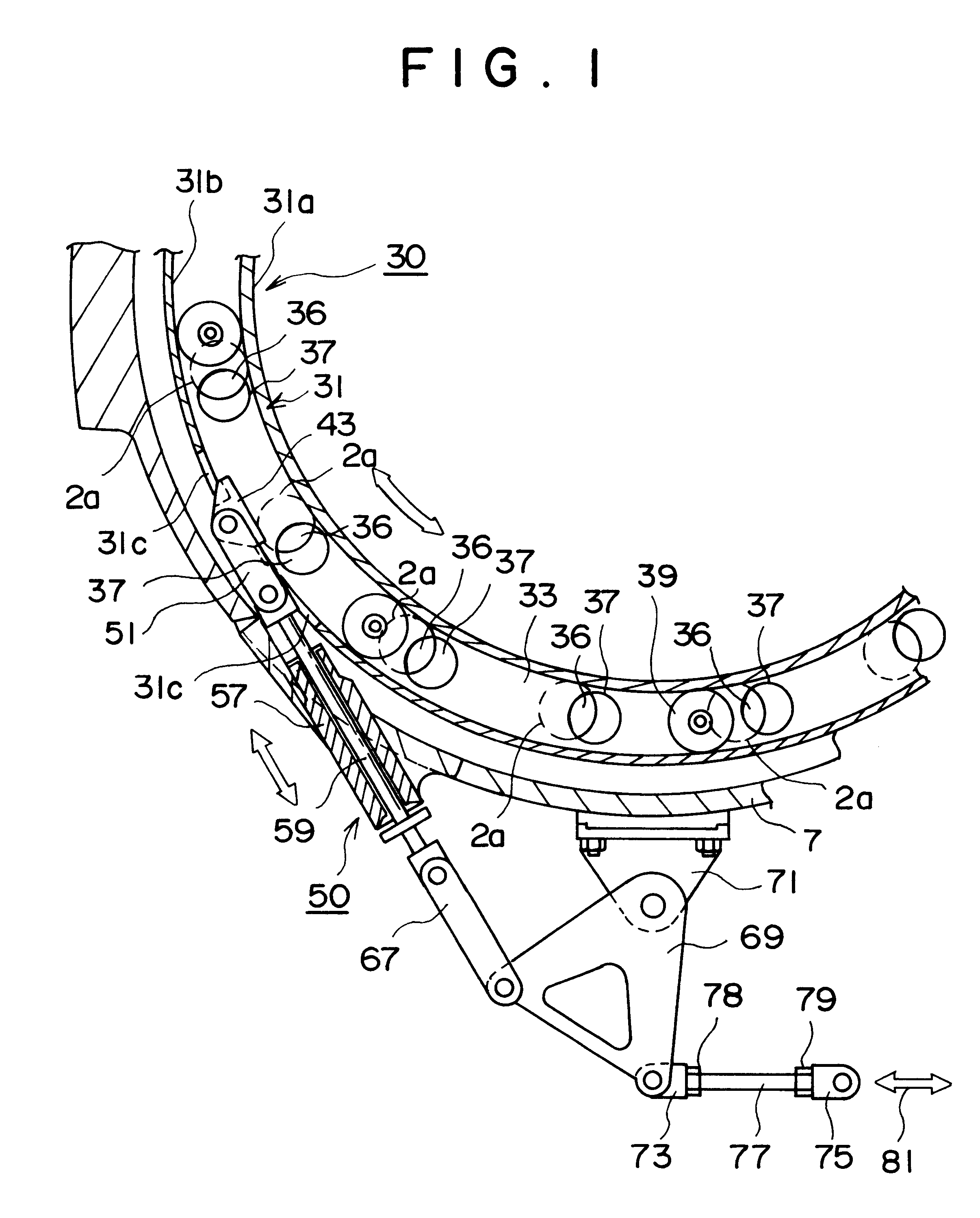
The object of this invention is to provide a bypass air control device for controlling the volume of air bypassed used in the combustion engine of a gas turbine in which, even when the combustion vibration described above occurs, the structural components of the control valve and its related hardware would not experience vibration, and in which the opening and closing of the bypass could be controlled in a reliable and stable fashion.

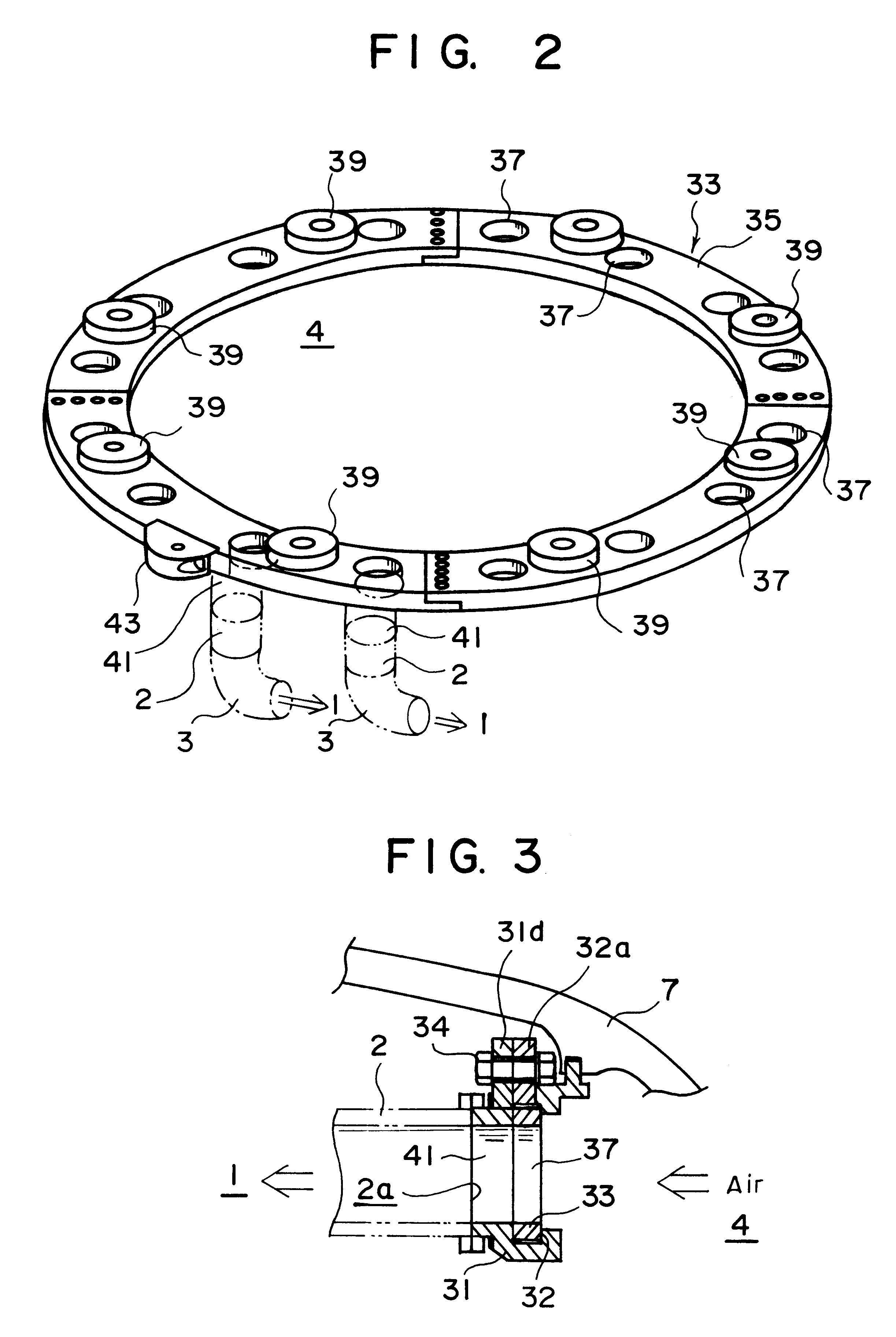
Another object of this invention is to provide a bypass air control device for controlling the volume of air bypassed in which the links or other connectors between the valve in the bypass channel for controlling the volume of air and the mechanism for adjusting that valve, which is placed on the exterior surface of the casing, can easily absorb any thermal expansion or assembly error which might occur.

Still other objects of this invention will be made clear from the disclosure which follows.

To achieve these objects, the present invention has been desig...


PUM


Abstract

The invention applies to an air bypass control device which can bypass a portion of the compressed air in the space within the casing into the tail pipe connected to a combustion chamber via a control valve and a bypass channel. The invention includes a valve mechanism including a flat sliding ring, and a valve operating mechanism. The valve mechanism intersects a number of bypass air channels each of which is connected to a pipe located in the space inside the casing. A number of openings are arranged in the flat sliding ring for bypassing the air to the bypass air channels. The valve operating mechanism, one end of which is connected to the flat sliding ring, causes the flat sliding ring to rotate back and forth. When the operating mechanism rotates the flat sliding ring, the openings in the flat sliding ring rotate so as to coincide with or move away from the openings of the bypass channels. The control valve mechanism is made up of a flat sliding ring with a number of openings which corresponds to the number of bypass channels, and a ring supporting base which supports the flat sliding ring in such a way that the flat sliding ring can slide freely in the circumferential direction. One side of the openings of the flat sliding ring opens into the space in the casing, and the other side of the openings opens into the opening of the bypass channel when it is rotated.

Description

This invention concerns a bypass air control device used to control the volume of air bypassed from the combustion engine in a gas turbine. More specifically, it concerns a bypass air control device which bypasses a volume of compressed air in the casing of the combustion engine, in which a number of combustion chambers are arranged with tail pipes, by diverting the compressed air into those tail pipes.TECHNICAL BACKGROUNDThe gas turbines used in electric power plants, nuclear power plants and various other industrial plants are velocity-type heat engines which employ as their operating medium their own operating gases, mainly air and combustion gases. These turbines basically comprise a compressor, which performs the adiabatic compression process; a combustor, which heats the air-fuel mixture under constant pressure; and a turbine, which performs the adiabatic expansion process.The combustor has a number of combustion chambers, each with a tail pipe, in the space in the casing whic...

Claims


Application Information

Patent Timeline
IPC IPC(8): F23M5/08F23R3/02F23R3/00F23R3/26F23M5/00
CPCF23M5/085F23R3/00F23R3/26
Inventor ICHIRYU, TAKUYASHIKI, TADAO
Owner MITSUBISHI HITACHIPOWER SYST LTD
Features
  • R&D
  • Intellectual Property
  • Life Sciences
  • Materials
  • Tech Scout
  • Unparalleled Data Quality
  • Higher Quality Content
  • 60% Fewer Hallucinations
Learn More