
Source-coupled logic with reference controlled inputs

a source-coupled logic and reference control technology, applied in logic circuit coupling/interface arrangement, instruments, pulse techniques, etc., can solve the problem of not fulfilling the promise of high speed that one, current-mode logic, uses a differential form of logic that is not as flexible and easy-to-use as reference controlled or "single-ended" logi

Inactive Publication Date: 2001-05-08
WERKING PAUL M
View PDF3 Cites 5 Cited by
  • Summary
  • Abstract
  • Description
  • Claims
  • Application Information

AI Technical Summary

Problems solved by technology

The SCL of the prior art succeeds at maintaining and improving the low noise characteristics of this architecture but does not fulfill the promise of high speed that one would expect from a current-mode logic.
In addition, it uses a differential form of logic that is not as flexible and easy-to-use as a reference controlled or "single-ended" logic.
While the use of two voltages to convey one signal can present several problems, it greatly simplifies the bias circuit.

Method used


Image

  • Source-coupled logic with reference controlled inputs
  • Source-coupled logic with reference controlled inputs
  • Source-coupled logic with reference controlled inputs

Examples


Embodiment Construction

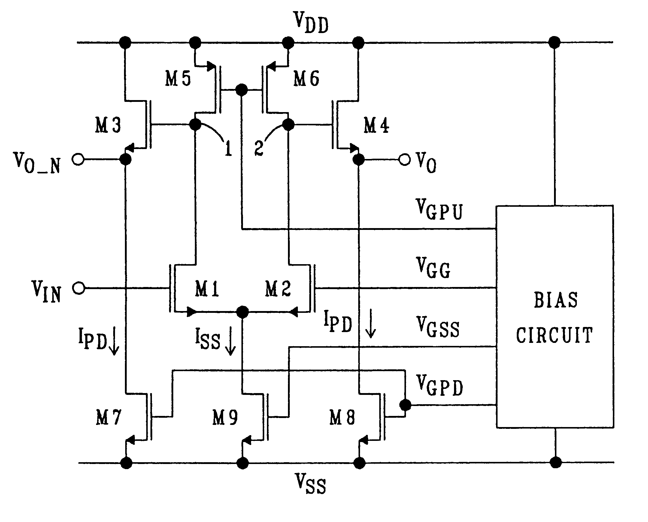
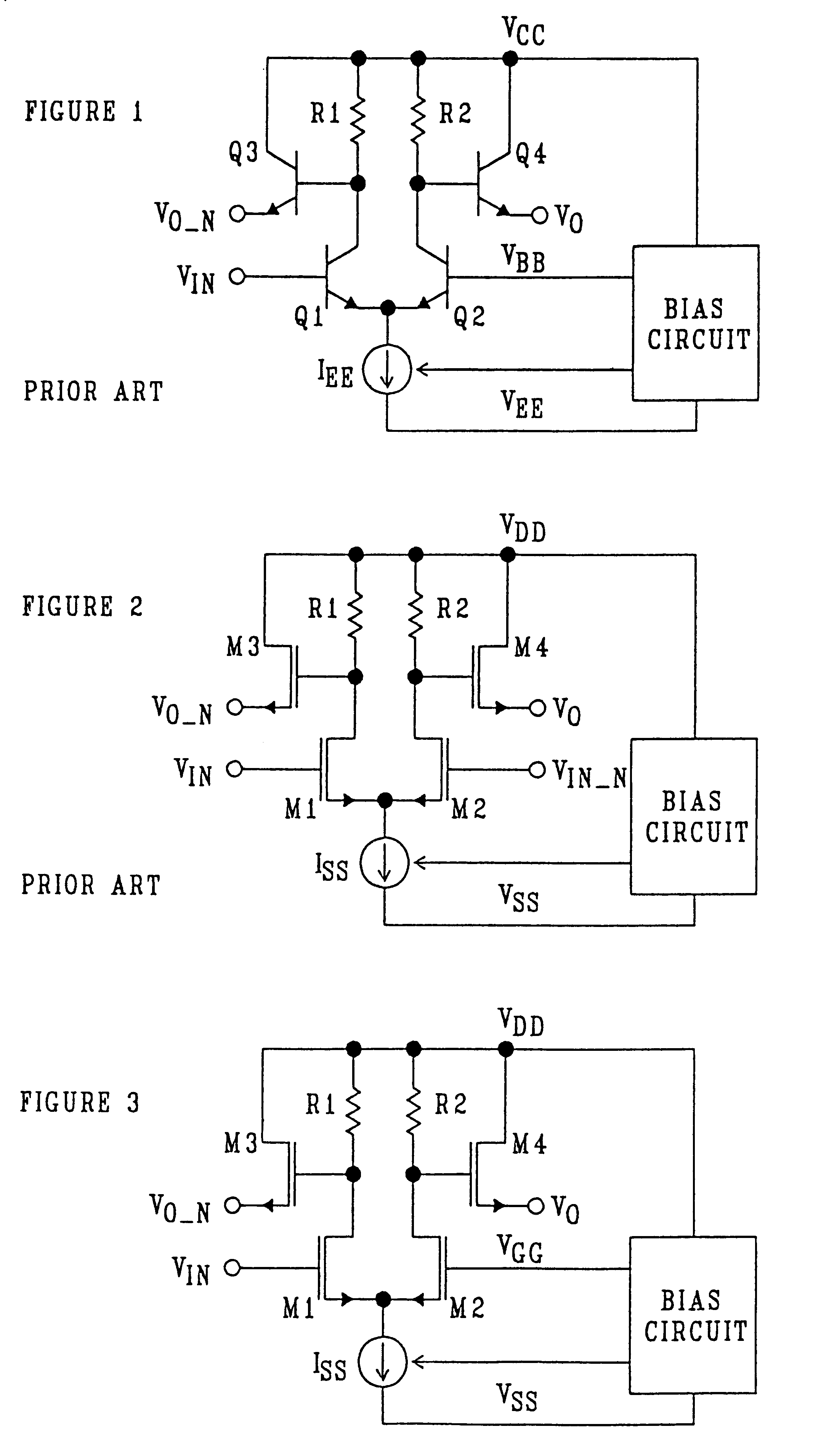
The essential elements of an inverter / buffer circuit using the reference controlled source-coupled logic (SCL) of this invention are shown in FIG. 3. (See also [6].) The operation of this circuit is similar to that of the ECL inverter / buffer of FIG. 1. When the input voltage, V.sub.IN, is less than that of a reference voltage, V.sub.GG, the common source bias current, I.sub.SS, flows through transistor M2 but not M1 resulting in a low voltage at the non-inverting output, V.sub.O, and a high voltage at the inverting output, V.sub.O.sub..sub.-- .sub.N. When V.sub.IN >V.sub.GG the opposite occurs: V.sub.O assumes a high, logic 1, voltage and V.sub.O.sub..sub.-- .sub.N assumes a low, logic 0, voltage.

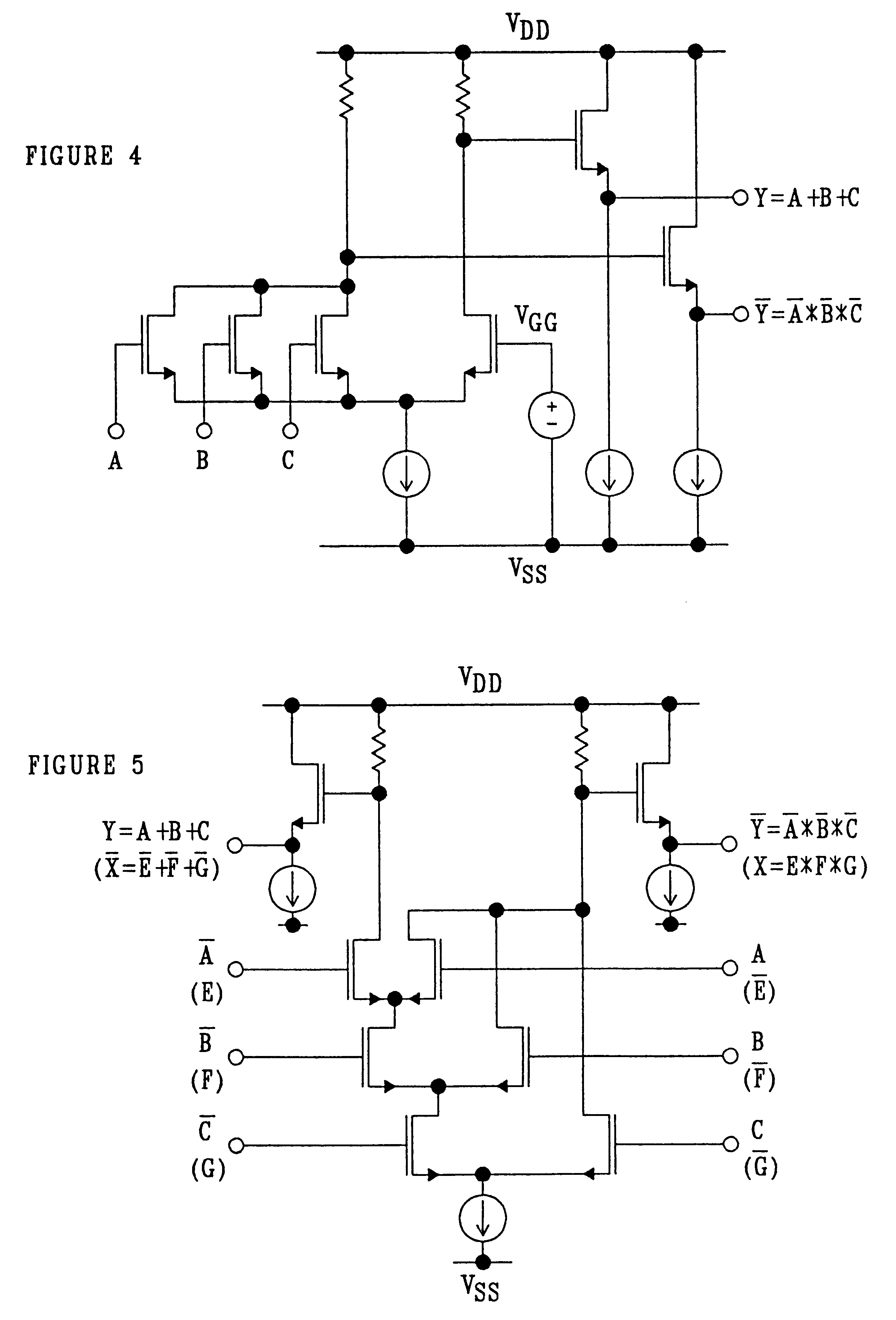
One difference between this invention and the prior art of FIG. 2 is the use of a voltage reference, V.sub.GG, supplied by a bias circuit. The importance of this voltage reference is illustrated in FIGS. 4 and 5. Both figures show the essential elements of a three-input OR / NOR gate. A refer...


PUM


Abstract

This invention relates to source-coupled logic (SCL) which is a functional derivative of emitter-coupled logic (ECL). ECL is widely recognized as having the characteristics of high speed (low propagation delay) and low power supply noise generation. The SCL of the prior art succeeds at maintaining and improving the low noise characteristics of this architecture but does not fulfill the promise of high speed that one would expect from a current-mode logic. In addition, it uses a differential form of logic that is not as flexible and easy-to-use as a reference controlled or "single-ended" logic. The SCL disclosed here has the desired high speed properties and maintains the ease of use that is a property of reference controlled ECL. In addition, the reference controlled SCL of this invention provides new capabilities that make it even more flexible than ECL in generating logical switching functions.

Description

1. Field of the InventionThis invention relates generally to digital logic circuits and more particularly relates to a MOSFET source-coupled logic circuit which is faster, can be implemented with fewer transistors and avoids double-ended or complementary differential logic.2. Description of the Related ArtThis invention relates to source-coupled logic (SCL) which is a functional derivative of emitter-coupled logic (ECL). ECL is widely recognized as having the characteristics of high speed (low propagation delay) and low power supply noise generation. The SCL of the prior art succeeds at maintaining and improving the low noise characteristics of this architecture but does not fulfill the promise of high speed that one would expect from a current-mode logic. In addition, it uses a differential form of logic that is not as flexible and easy-to-use as a reference controlled or "single-ended" logic. The SCL disclosed here has the desired high speed properties and maintains the ease of us...

Claims


Application Information

Patent Timeline
Patent Type & Authority Patents(United States)
IPC IPC(8): G05F3/08G05F3/24H03K19/094H03K19/0185
CPCG05F3/247H03K19/018514H03K19/09432
Inventor WERKING, PAUL M.
Owner WERKING PAUL M
Learn More