Vehicle-detecting unit for use with electronic parking meter

a technology for parking meters and vehicle detection, which is applied in traffic control systems, transportation and packaging, instruments, etc., can solve problems such as tampering with meters, obstacles in the meter/space environment, and the inability to achieve actual results

Inactive Publication Date: 2001-05-08
INTELLIGENT DEVICES INC
View PDF34 Cites 151 Cited by
  • Summary
  • Abstract
  • Description
  • Claims
  • Application Information

AI Technical Summary

Benefits of technology

It is still another object of this invention to provide a vehicle detector unit that does not have to be precisely aimed in order to detect the presence or absence of vehicles in the corresponding parking space.
It is another object of this invention to provide a vehicle detector unit that provides any electronic parking meter with the ability to detect the presence or absence of vehicles in the corresponding parking space without the need to modify the hardware of the electronic parking meter.

Problems solved by technology

However, all of the above references suffer from one of many different problems and actually achieving this objective remains elusive.
The reasons for not being able to implement such a working vehicle detector include: the uncertainty of the parking meter location and of the parking meter / space environment, vehicles that are parked too far back in the parking space, the smoothness of the surfaces of different vehicles, the "fast parker", the inadvertent or intentional presence of a person in front of the meter and tampering with the meter including the vandalizing of the sensor itself.
Furthermore, the vehicle-detecting parking meter must be able to provide a reliable vehicle-detection scheme that uses low power since the parking meter is a stand-alone device that does not have the luxury of using utility power.
In particular, the environment of the meter / space presents obstacles that must be recognized and compensated for, or distinguished, by the vehicle detector.
For example, the road may be very steeply-crowned and an ultrasonic-based vehicle detector will receive reflections from the crowned road, and may erroneously conclude that a vehicle is in the corresponding parking space when there truly is no vehicle there.
Another example, is that if trash bins, light posts, trees, sign posts, etc. are closely-adjacent the parking meter, almost any wireless vehicle detection scheme will be subjected to sufficient interferences from these, thereby causing the detector to make erroneous conclusions about the presence / absence of a vehicle in the parking space.
Even the sensor used to implement the vehicle detection suffers from its own respective drawbacks.
For example, the use of RADAR (radio detection and ranging) suffers from such things as possible interferences from other RADAR-vehicle-detecting units, frequency band licensing concerns as well as cost.
The use of optical sensors in vehicle detection (e.g., U.S. Pat. No. 4,043,117 (Maresca)) suffer from receiving reflections that may vary from strong reflections (reflected off of vehicle glass) versus weak reflections (reflected off the body of a very dark-colored vehicle), which are hard to detect.
Videocamera / processing when used for vehicle detection (e.g., U.S. Pat. No. 5,777,951 (Mitschele et al.)) is not only very expensive but in those cases where the video camera is positioned to capture the front-end vehicle license plate, in those states where front-end vehicle license plates are not required, identification of the vehicle is thwarted.
However, some of the problems with such a method are the following: certain vehicles disperse the interrogating signal, rather than returning a strong reflection; another problem is that to compensate for adjacent obstacles, e.g., crowned-street, tree, sign post, etc., the sensitivity of the sensor has to be reduced by raising the threshold but in doing so, even more vehicles are not properly detected; the reflected signals, or echos, are inherently unstable, i.e., the movement of air and even very minute physical movements in the environment make these signals unstable.
Furthermore, some echos cancel other echos and exhibit multi-path problems, thus making the echos unstable.
As a result, there is no teaching or suggestion that each sensor act as both a transmitter / receiver for a signal that monitors a particular portion of the parking space.
Another problem that is encountered with such vehicle detection systems is a "fast-parker" scenario, i.e., a vehicle pulling into a parking space that has just been emptied but before the vehicle detector has determined that the first vehicle has departed.
However, various problems exist with the use of solar power sources including the use of parking meters in shady areas, or the use of parking meters during periods in which there is very little sunlight.
This causes the rechargeable batteries to run down, and they require frequent replacement.
Or, in the case of the use of capacitors, the lack of power causes the meter to become inoperative.

Method used


Image

  • Vehicle-detecting unit for use with electronic parking meter
  • Vehicle-detecting unit for use with electronic parking meter
  • Vehicle-detecting unit for use with electronic parking meter

Examples


Embodiment Construction

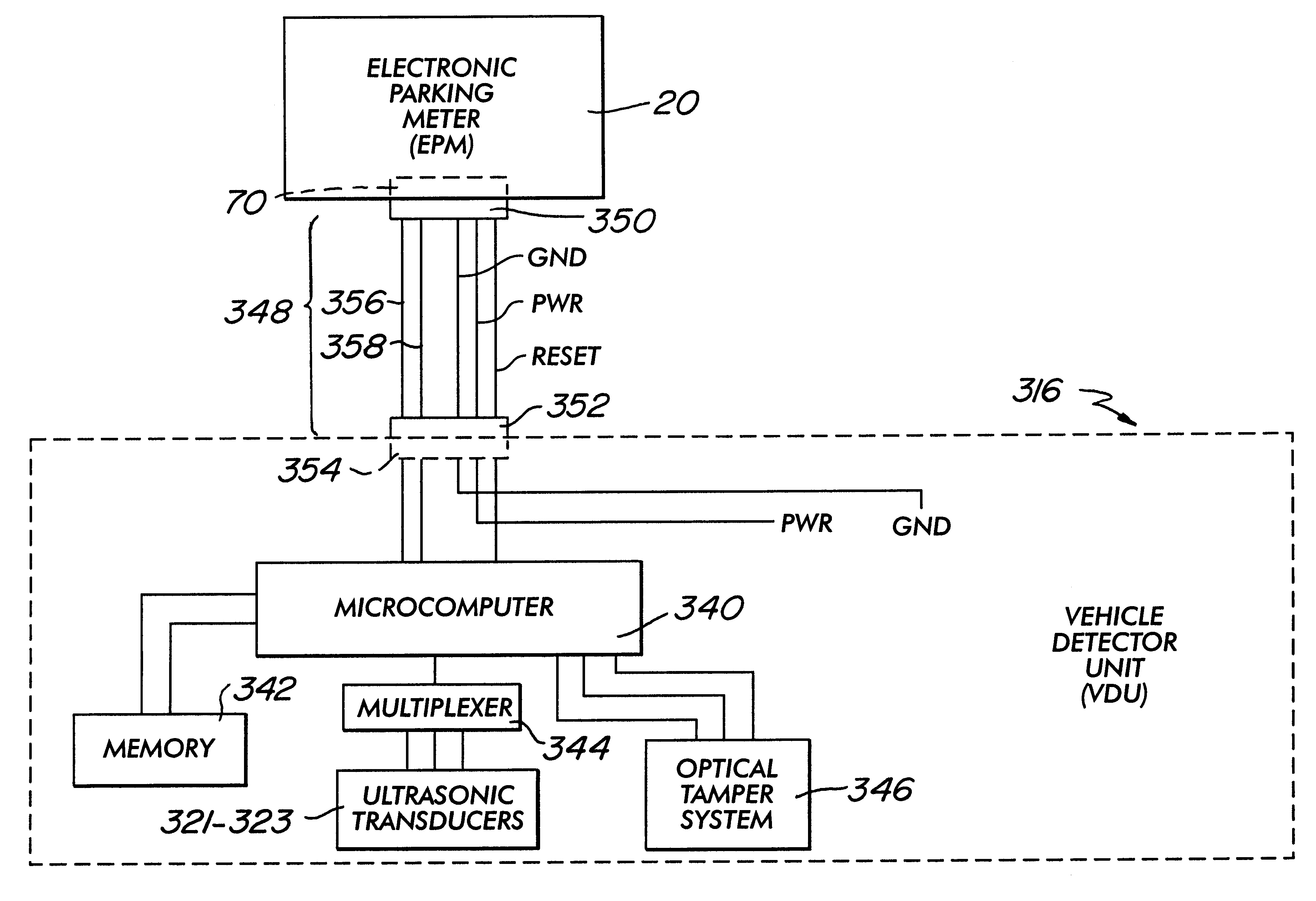
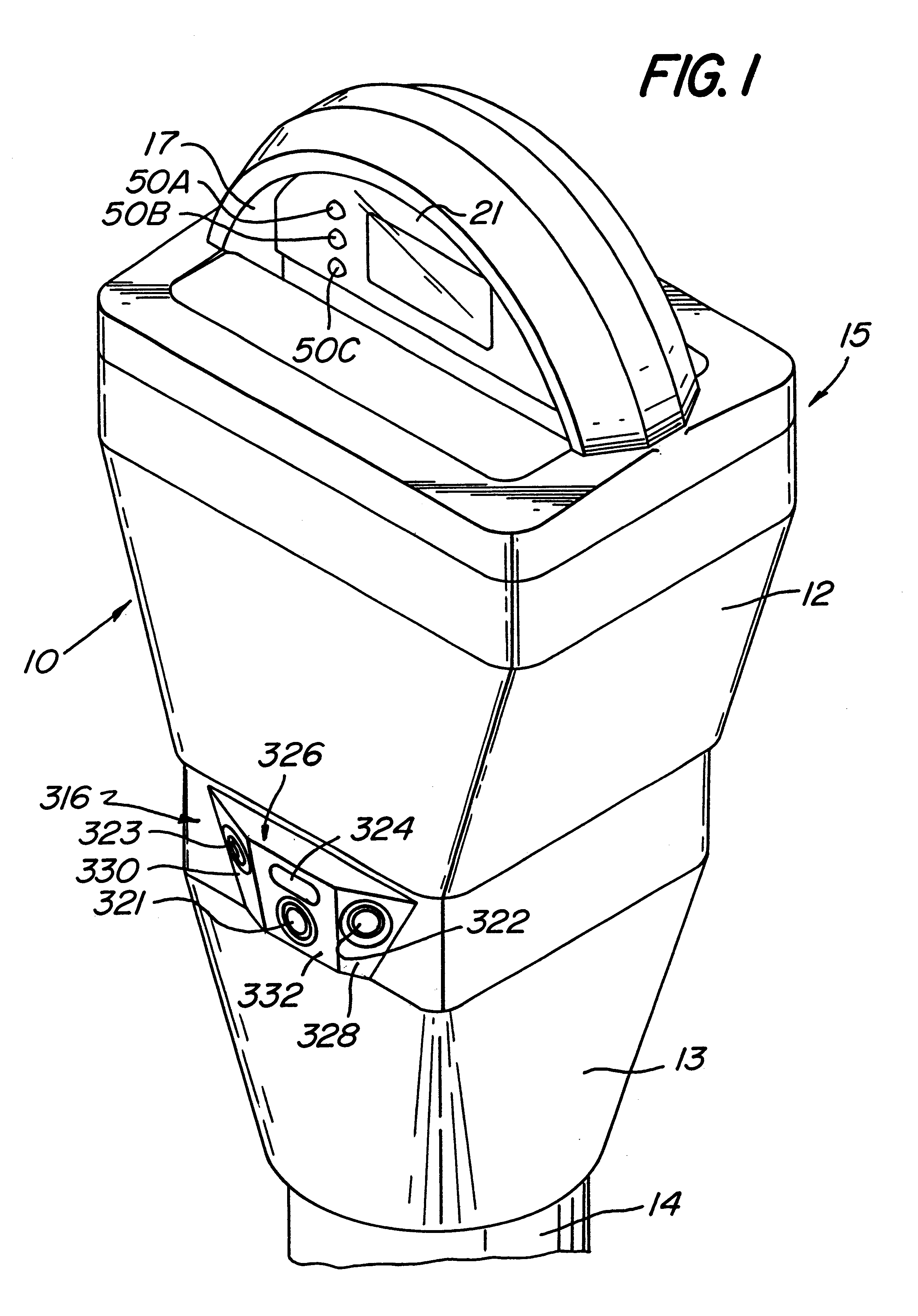
Referring now in greater detail to the various figures of the drawing wherein like reference characters refer to like parts, a vehicle detector unit (hereinafter "VDU") for use with electronic parking meters constructed in accordance with the present invention is shown generally at 316 in FIG. 1. The VDU 316 issued in conjunction with a parking meter 10 to provide the parking meter 10 with vehicle detection capability. As shown most clearly in FIG. 1, the parking meter 10 comprises a parking meter housing 12 that is supported at the parking space location (not shown) by a stanchion 14. The parking meter housing 12 is coupled to the stanchion 14 via a vault 13 (which receives the deposited coins) and the VDU 316.

The operative part of the parking meter, hereinafter known as the electronic parking meter (EPM) (see FIG. 5; an example of such an EPM is the tool-less parking meter mechanism, TLPMM 20, disclosed in A.S.N. 09 / 231,718 but it should be understood that any electronic parking m...


PUM


Abstract

A vehicle detector unit and detection method for use with an electronic parking meter for providing the electronic parking meter with the ability to reliably detect the presence or absence of a vehicle in any existing corresponding parking space, independent of the surrounding environment, while using a minimum of power.

Description

This invention relates generally to the field of parking meters and more particularly to electronic parking meters that can detect parked vehicles.Parking meters permit vehicles to be parked on streets for an allowable time determined by the number and denominations of coins which are placed in the parking meter. A clock mechanism in the parking meter runs down the allowable time until it reaches zero, and an overtime parking indication appears.It has been long recognized that if the parking meter were able to detect the presence or absence of the vehicle, either by mechanical means or wireless means, in the corresponding parking space, then among other things, the parking meter could be reset, thereby requiring the next patron to insert the appropriate amount of payment for his / her parking time. U.S. Pat. No. 3,015,208 (Armer); U.S. Pat. No. 3,018,615 (Minton et al.); U.S. Pat. No. 3,034,287 (Odom et al.); U.S. Pat. No.3,054,251 (Handley et al.); U.S. Pat. No. 3,064,416 (Armer); U....

Claims


Application Information

Patent Timeline
Patent Type & Authority Patents(United States)
IPC IPC(8): G07F17/00G07F17/24
CPCG07F17/24G07F17/246
Inventor YOST, VINCENT G.SAAR, DAVID A.
Owner INTELLIGENT DEVICES INC
Why Eureka
Try Eureka