Driving circuit and driving method for piezoelectric transformer, backlight apparatus, liquid crystal display apparatus, liquid crystal monitor, and liquid crystal TV

a piezoelectric transformer and circuit technology, applied in the field of piezoelectric transformers, can solve the problems of affecting the efficiency of the inverter circuit, and affecting the miniaturization of the inverter circuit, and achieves the effects of low distortion, high frequency precision, and high efficiency

Inactive Publication Date: 2006-04-25
PANASONIC CORP
View PDF21 Cites 19 Cited by
  • Summary
  • Abstract
  • Description
  • Claims
  • Application Information

AI Technical Summary

Benefits of technology

[0029]Therefore, with the foregoing in mind, it is an object of the present invention to provide a driving circuit for a piezoelectric transformer that is capable of controlling the driving of a piezoelectric transformer with high efficiency and low distortion by digital control requiring no high frequency precision and being miniaturized; a backlight apparatus to which the driving circuit for a piezoelectric transformer is applied; a liquid crystal display apparatus in which the backlight apparatus is mounted; and a liquid crystal monitor and TV using the liquid crystal display apparatus.

Problems solved by technology

As a result, there is a possibility that driving is performed apart from a resonance frequency (herein, this refers to a frequency at which a voltage step-up ratio becomes maximum), which causes a decrease in efficiency or the like.
Furthermore, in order to solve the above-mentioned problem, it is required to add a circuit for regulating a power supply voltage, which hinders the miniaturization of an inverter circuit.
However, when a driving circuit is composed of one chip, a small package cannot be used due to the limitation of the number of pins; therefore, its effect is small.
However, harmonic components cannot be removed completely, and due to the sweep of a frequency, the harmonic of a driving frequency is matched with a vibration mode of the piezoelectric transformer during light-adjusment control of a cold-cathode fluorescent tube.
Consequently, waveform distortion of an input / output voltage and harmonic distortion of a piezoelectric transformer occur.
Due to the problem of distortion caused by the large amplitude operation, there is a limitation to the miniaturization of the piezoelectric transformer.
This causes a large amplitude operation, making it difficult to miniaturize the piezoelectric transformer.
However, in the case where waveform processing is performed with an input voltage, as described in (2), waveform distortion occurs due to a harmonic component, and it becomes difficult to reduce waveform distortion during steady operation.

Method used


Image

  • Driving circuit and driving method for piezoelectric transformer, backlight apparatus, liquid crystal display apparatus, liquid crystal monitor, and liquid crystal TV
  • Driving circuit and driving method for piezoelectric transformer, backlight apparatus, liquid crystal display apparatus, liquid crystal monitor, and liquid crystal TV
  • Driving circuit and driving method for piezoelectric transformer, backlight apparatus, liquid crystal display apparatus, liquid crystal monitor, and liquid crystal TV

Examples


embodiment 1

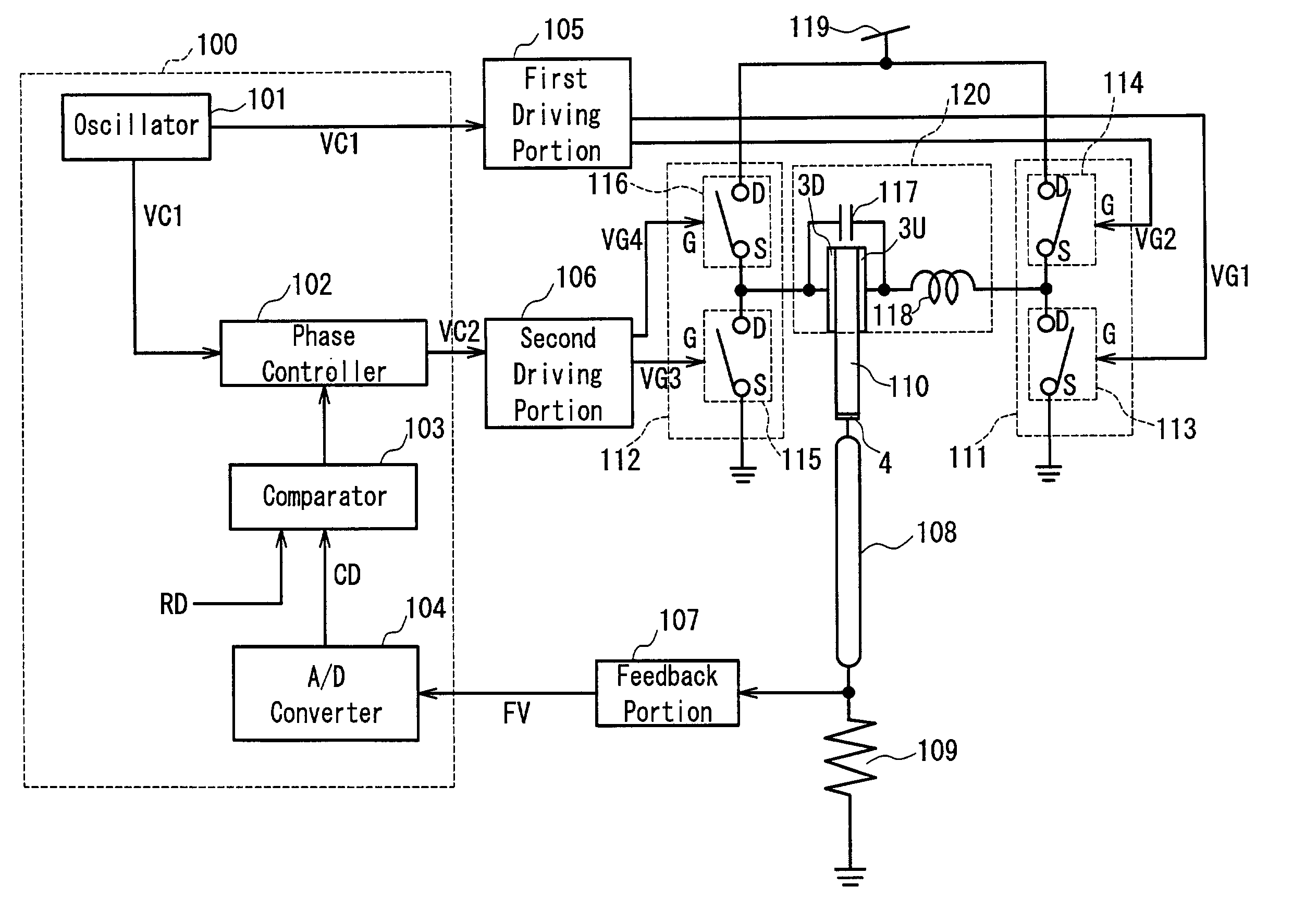
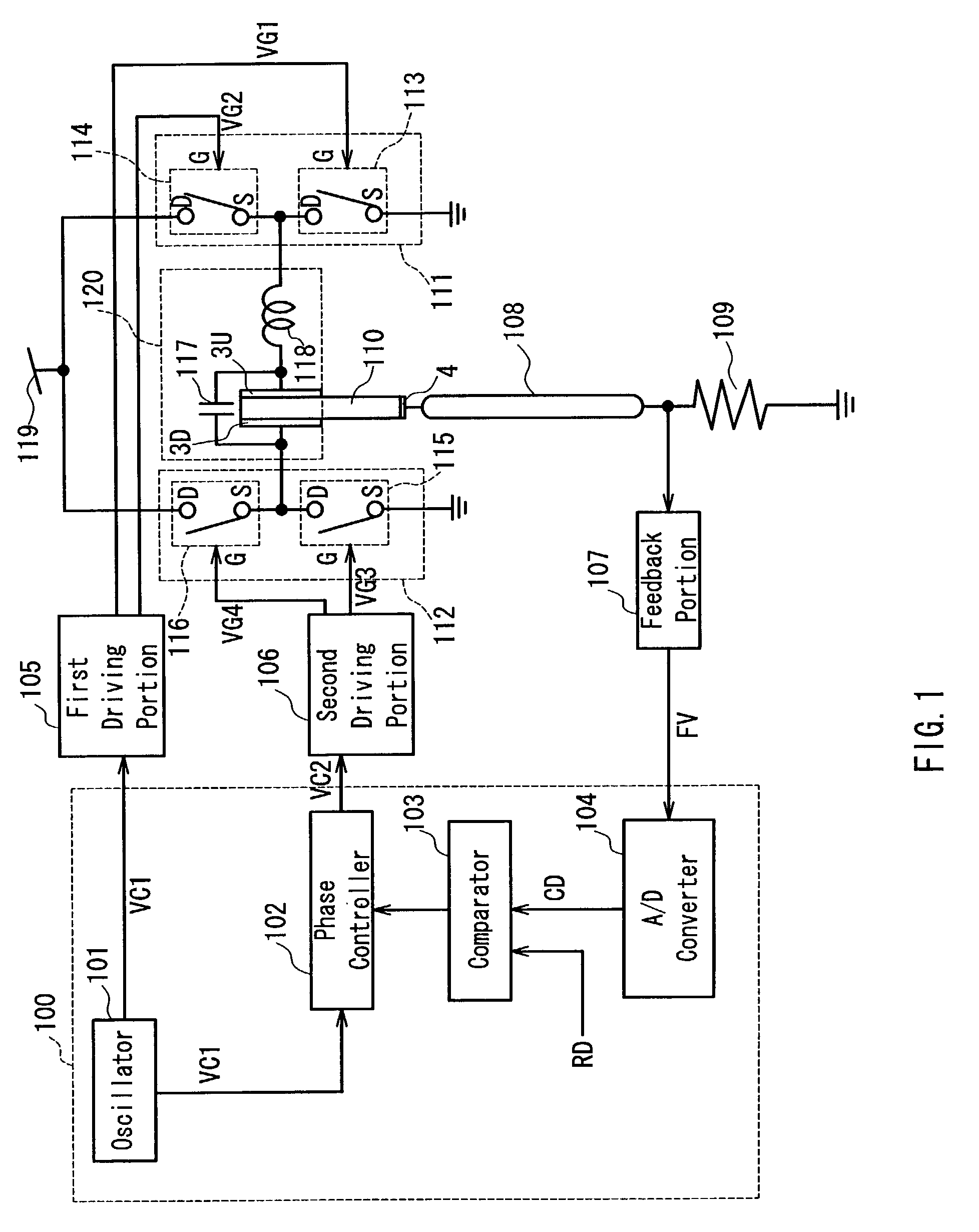
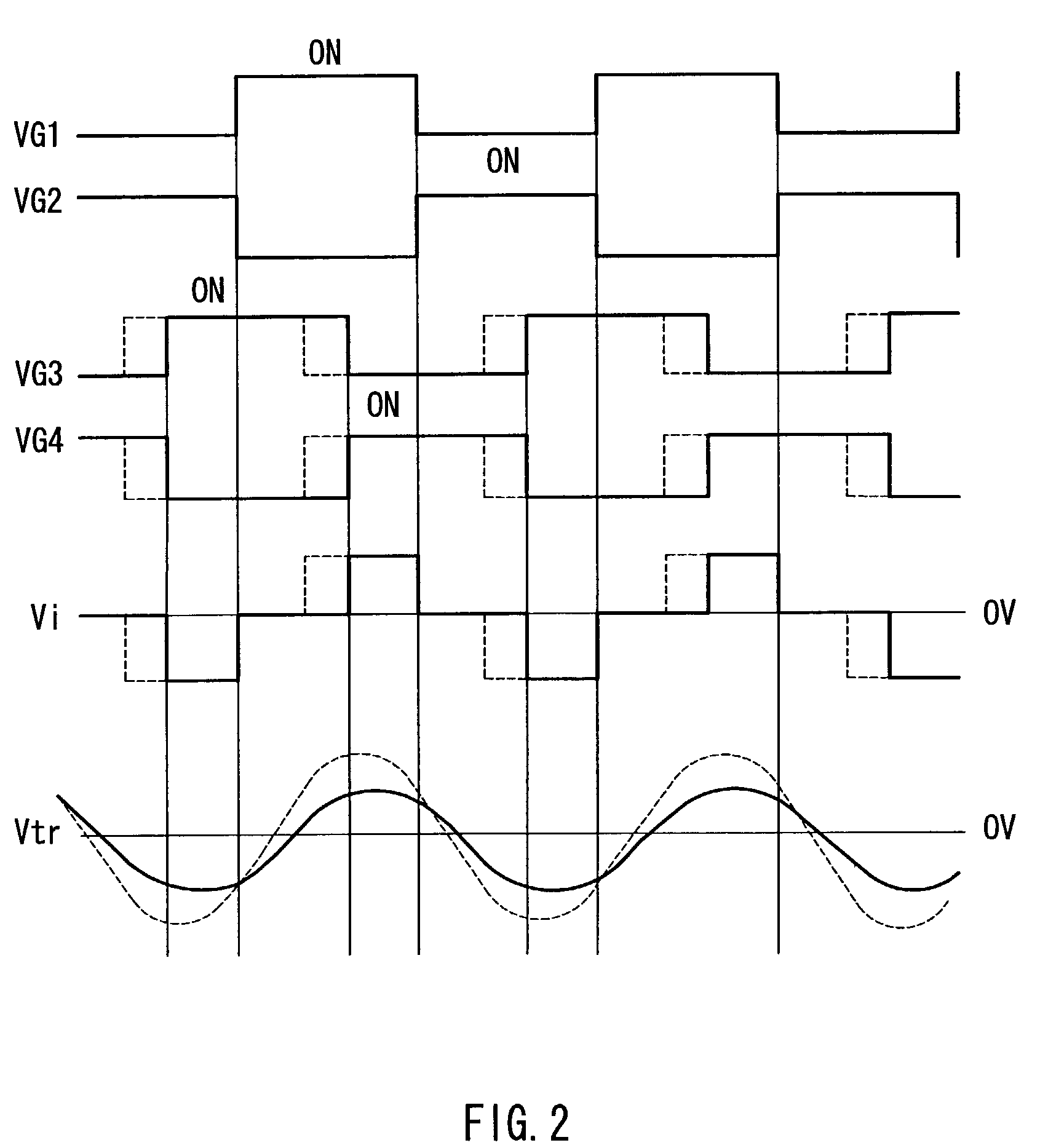
[0116]FIG. 1 is a block diagram showing an exemplary configuration of a driving circuit for a piezoelectric transformer of Embodiment 1 according to the present invention. The piezoelectric transformer used in the present embodiment has the same configuration and operation as those shown in the prior art, so that its description will be omitted here.

[0117]In FIG. 1, a digital controller 100 is composed as a part of microcomputer (hereinafter, abbreviated as a “μCOM”), and includes an oscillator 101, a phase controller 102, a comparator 103, and an A / D converter 104. The oscillator 101 generates an AC driving signal driving a piezoelectric transformer 110. An output signal from the oscillator 101 is input directly to a first driving portion 105 and is input to a second driving portion 106 via the phase controller 102. The phase controller 102 receives an output signal from the comparator 103 and outputs an AC signal, which has the same frequency as and a different phase from those of...

embodiment 2

[0155]FIG. 11 is a block diagram showing an exemplary configuration of a driving circuit for a piezoelectric transformer of Embodiment 2 according to the present invention. In FIG. 11, the present embodiment is different from Embodiment 1 in that a comparator 203 receiving two reference data RD1 and RD2 is provided in the digital controller 200. Furthermore, the present embodiment is different from Embodiment 1 in a control method at a time of commencement of lighting of the cold-cathode florescent tube 108. The other components and functions are the same as those in Embodiment 1. The same components are denoted with the same reference numerals, and the description thereof will be omitted here.

[0156]FIG. 12 shows a relationship between frequency characteristics of a voltage step-up ratio and a driving frequency of the piezoelectric transformer 110. A curve TP202 represents frequency characteristics before a current flows through the cold-cathode fluorescent tube 108. Since it is alm...

embodiment 3

[0171]FIG. 17 is a block diagram showing an exemplary configuration of a driving circuit for a piezoelectric transformer of Embodiment 3 according to the present invention. In FIG. 17, the present embodiment is different from Embodiment 2 in that the oscillation frequency at an oscillator 301 is controlled by a signal from a comparator 303 at the commencement of lighting of the cold-cathode fluorescent tube 108. The other components and functions are the same as those in Embodiment 2. The same components are denoted with the same reference numerals, and the description thereof will be omitted here.

[0172]FIG. 18 shows a relationship between frequency characteristics of a voltage step-up ratio and a driving frequency of the piezoelectric transformer 110. In FIG. 18, a curve TP301 represents frequency characteristics before a current flows through the cold-cathode fluorescent tube 108. Since it is almost under a no-load condition until a current starts flowing through the cold-cathode ...


PUM

PropertyMeasurementUnit
switching frequencyaaaaaaaaaa
thicknessaaaaaaaaaa
widthaaaaaaaaaa

Abstract

A driving circuit for a piezoelectric transformer is provided, which is capable of driving a piezoelectric transformer at a high efficiency and with low distortion, and being miniaturized. At the commencement of lighting a cold-cathode fluorescent tube, a digital controller fixes frequencies of first and second control signals VC1 and VC2 at a predetermined frequency and controls the phase difference therebetween so that an output power of the piezoelectric transformer becomes from substantially zero to a predetermined output power. After lighting of the cold-cathode fluorescent tube, the digital controller controls the phase difference between the first and second control signals VC1 and VC2 so that current detecting data CD substantially is matched with reference data RD.

Description

BACKGROUND OF THE INVENTION[0001]1. Field of the Invention[0002]The present invention relates to a liquid crystal backlight apparatus, and more specifically, to a backlight apparatus for a personal computer, a liquid crystal monitor, and a liquid crystal TV.[0003]2. Description of the Related Art[0004]FIG. 26 shows a configuration of a Rosen type piezoelectric transformer, which is a typical configuration of a conventional piezoelectric transformer. This piezoelectric transformer enables a very high voltage step-up ratio to be obtained when a load is infinite and enables a voltage step-up ratio to be decreased when a load becomes smaller. Furthermore, the piezoelectric transformer has the following advantages: it can be miniaturized compared with an electromagnetic transformer, is nonflammable, and does not generate noise due to electromagnetic induction. Because of these features, the piezoelectric transformer has been used as a power source for a cold-cathode fluorescent tube.[000...

Claims


Application Information

Patent Timeline
Patent Type & Authority Patents(United States)
IPC IPC(8): G09G3/36G09G5/00H01L41/04H05B41/16G02F1/133G09G3/34H05B41/282H05B41/392
CPCH05B41/2827H05B41/3925H05B41/2828Y02B20/186Y02B20/00G02F1/133
Inventor NAKATSUKA, HIROSHITAKEDA, KATSUISHIKAWA, TAKASHIMORITOKI, KATSUNORI
Owner PANASONIC CORP
Why Eureka
Try Eureka