Stage for a workpiece

a technology for workpieces and stages, applied in the direction of dynamo-electric machines, maintainance and safety accessories, large fixed members, etc., can solve the problems of significant differences in the thermal characteristics of steel rails, errors in the accuracy of processing workpieces, etc., and achieve the effect of improving guidance accuracy and benefiting from the stage construction

Inactive Publication Date: 2005-04-07
LEICA MICROSYST LITHOGRAPHY
View PDF5 Cites 2 Cited by
  • Summary
  • Abstract
  • Description
  • Claims
  • Application Information

AI Technical Summary

Benefits of technology

[0011] The advantages of use of this metal matrix composite in the stage construction are particularly evident in a stage for translational workpiece displacement in which the relative movement of the members is substantially rectilinear. The guide means in such a case are then elongate and may take the form of track elements, which are fixed to the members and define tracks, and rollable elements co-operable with the tracks. Guidance accuracy can be enhanced by use of two spaced apart and parallelly extending sets of such track elements. At least some of the track elements can be seated in grooves in the members, which provides particularly secure seating of the track elements without undue risk of warping of the elements, as could occur in the past, due to differential expansion of the material of the elements and that of the member or members with the grooves.
[0012] In a simple stage construction the lower member is a fixed base plate and the upper member is thus the sole movable stage component unless, for example, it carries a workpiece support which is separately movable. In a preferred stage construction, however, the stage comprises a fixed base distinct from the upper and lower members and further such guide means, for example track elements and co-operating rollable elements, serving to mount the lower member on the base plate to be displaceable relative thereto. In that case the upper member is preferably displaceable relative to the lower member in a first direction and the lower member displaceable relative to the base plate in a second direction substantially orthogonal to the first direction. Such a stage is thus capable of imparting translation motion to a supported workpiece in X and Y directions. Optimised matching of the coefficients of thermal expansion of the principal adjoining components, i.e. members, base plate and both guide means, can be achieved if not only the two members, but also the base plate are made of the composite.
[0013] The invention also embraces a machine comprising a stage with the constructional features outlined above, the benefit of the stage construction being particularly evident in applications where precise guidance of a supported workpiece is highly critical, for example in an electron beam lithography machine. Such machines can be employed for writing patterns on substrates with an accuracy in the nanometre range, in which case even minute deviations in stage guidance accuracy can have a deleterious influence on accuracy of pattern detail to the extent of obliging complicated and time-consuming positional corrections.

Problems solved by technology

Such rails, if of steel, are liable to have significantly different thermal characteristics relative to the tables to which they are attached, particularly if the tables are of aluminum.
This undesired differential expansion prejudices the precision of the table guidance and ultimately represents a source of error in the accuracy of processing workpieces.
Such problems have not been addressed by material selections present in the prior art, for example U.S. Pat. No. 6,252,705, in which it is proposed to use beryllium copper alloy, phosphor bronze, non-magnetic steel alloys or even ceramic for guide rails, the selections, however, being stimulated by considerations relating to magnetic / non-magnetic properties rather than assimilation of coefficients of thermal expansion of adjoining components.

Method used


Image

  • Stage for a workpiece
  • Stage for a workpiece

Examples


Embodiment Construction

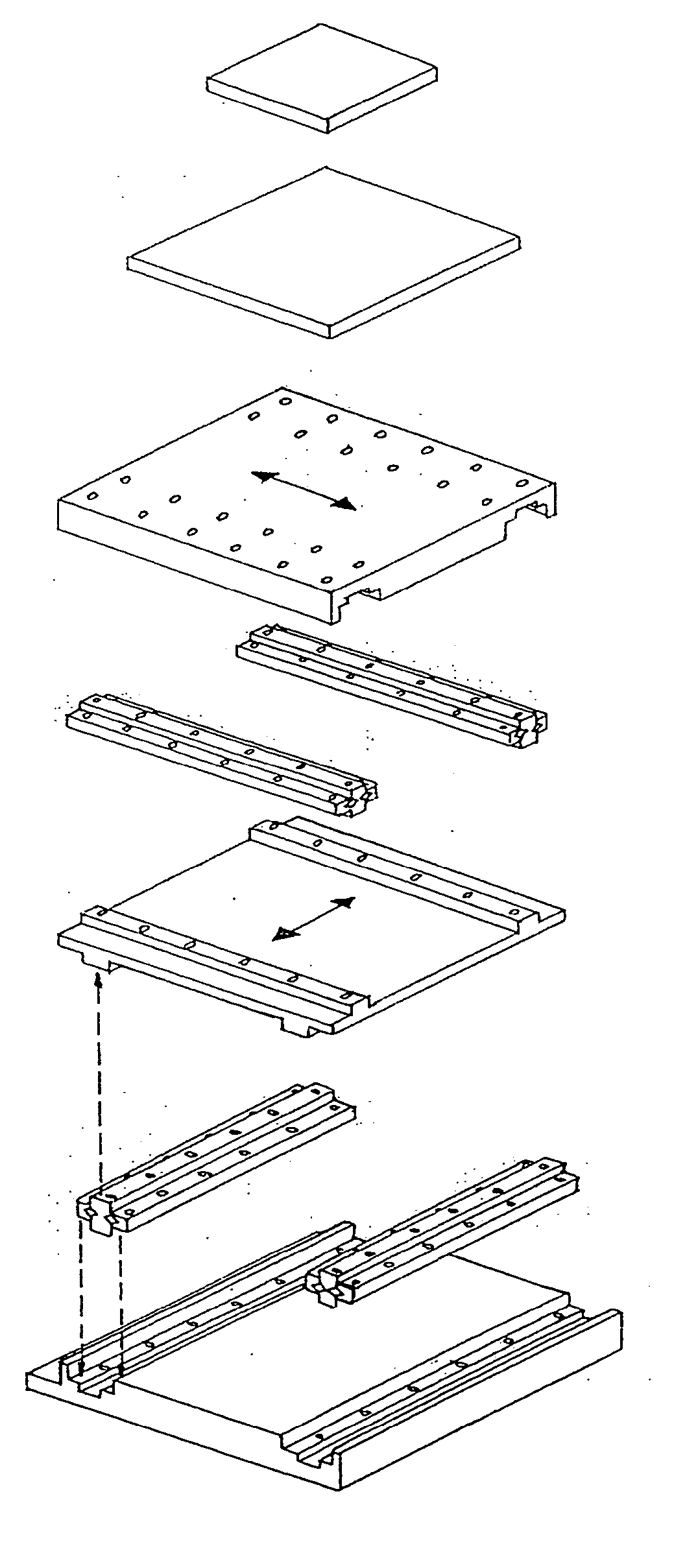
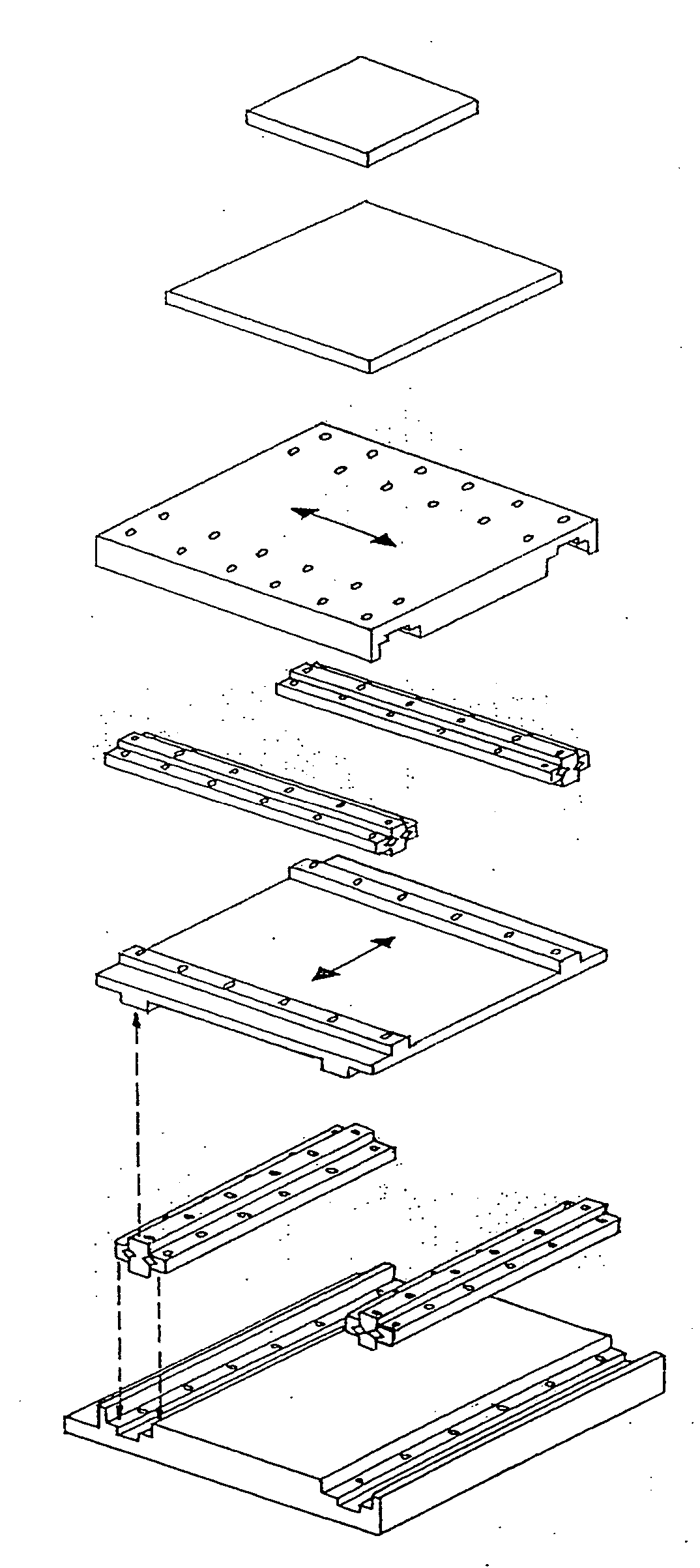
[0015] Referring now to the drawing there is shown, in exploded representation, a workpiece stage 10 for a machine tool or other form of machine, particularly a machine in which precise guidance of a workpiece in X and Y directions is required. Such a machine can be, for example, an electron beam lithography machine in which small-scale integrated circuit layouts are repeatedly written on successive substrates, such as semiconductor wafers. For the purpose of writing the circuit features, each wafer must be displaced in fine increments within very close ranges of tolerances with respect to pitch, roll and yaw so as to avoid offsets in mutually abutting pattern lines. The nature of the machine incorporating the stage and the manner in which the stage is utilised in the machine do not concern the invention as such. However, the stage construction is directed to, inter alia, minimising differential thermal expansion of adjoining stage components and the stage is thus particularly benef...


PUM


Abstract

A stage (10) for a workpiece comprises an upper member (13) for carrying a workpiece holder (15), a lower member (12) and two guide assemblies (16) mounting the upper member (13) on the lower member (12) to be rectilinearly displaceable relative thereto. The lower member (12) is in turn preferably similarly mounted on a fixed base plate (11) by further such guide assemblies (16), the two members (12, 13) being respectively displaceable in an X direction and a Y direction. At least one of the members (12 or 13), but preferably both members and also the base plate (11), is made of a machinable lightweight composite, for example aluminium alloy and silicon carbide, having a coefficient of thermal expansion not exceeding that of the principal material of the guide assemblies by more than substantially 50%, preferably by no more than 30 to 35%.

Description

RELATED APPLICATIONS [0001] This application claims priority of the British patent application 03 23 079.4 which is incorporated by reference herein. FIELD OF THE INVENTION [0002] The present invention relates to a stage for a workpiece, especially a stage for translational movement of a workpiece. BACKGROUND OF THE INVENTION [0003] Workpiece stages, particularly stages for translation movement of workpieces, but also stages for rotational movement or both translational and rotational movement, are used in a wide variety of machines for processing workpieces by mechanical action, such as cutting, milling and drilling, and by chemical, sonic, optical and electron bombardment action, for example etching, erosion and welding, to name only some more common forms of treatment. In most cases a requirement is present for accurate positioning of the workpiece and thus precisely guided movement. In some instances, particularly micro-treatment of extremely small workpieces, high-precision gui...

Claims


Application Information

Patent Timeline
Patent Type & Authority Applications(United States)
IPC IPC(8): B23Q1/01B23Q1/58B23Q1/62B23Q11/00H01L21/027
CPCB23Q11/0003B23Q1/58
Inventor HARRIS, PAUL
Owner LEICA MICROSYST LITHOGRAPHY
Why Eureka
Try Eureka