Toner image transfer apparatus

a technology of toner and image, applied in the direction of electrographic process apparatus, thin material processing, instruments, etc., can solve the problems of inability to make small-sized apparatus, leakage or the like, and the back surface of a sheet will be contaminated with toner or the lik

Inactive Publication Date: 2001-05-08
SHARP KK
View PDF6 Cites 3 Cited by
  • Summary
  • Abstract
  • Description
  • Claims
  • Application Information

AI Technical Summary

Problems solved by technology

However, problems such as leakage or the like occur due to generation of ozone and supplying of extremely high voltage.
Therefore, the back surface of a sheet will be contaminated by toner or the like unless the adhered toner is not removed.
However, when the photoreceptor is made large in diameter, peeling-off of a sheet problematically remains such that the apparatus cannot be made small-sized due to the need of provision of separate separation mechanism or the like.
In the case of using the transfer conveying belt, however, it is inevitably necessary to provide a cleaning device separate from a cleaning device on the side of the photoreceptor, so that it cannot be desired to further make the image forming apparatus small-sized.
Besides, the transfer conveying belt is formed to be exceedingly lengthy, which correspondingly makes the apparatus large.
As described above, a system, in which a transfer roller is brought into contact with a back surface of a sheet to transfer a toner image thereto, has advantages and disadvantages, so that it is not possible to perform high speed processing, make an apparatus small-sized, and suppress an increase in cost.
The use of a transfer belt system can omit a peeling-off mechanism, but the transfer belt is made lengthy, which does not make miniaturization.
Further, with an arrangement, in which toner or the like adhered to the transfer belt is transferred to the photoreceptor with a view to cleaning, cleaning takes time, and so the apparatus cannot cope with high speed running.
More specifically, in the case where there is not for suspension durations in a timing that a state, in which the transfer voltage is supplied, is changed over to the cleaning voltage, errors such as deviations of a transfer material, deviations in timing or the like would cause failure in transfer at a trailing end or a leading end of a recording material due to supplying of the cleaning voltage, and incapability of cleaning the transfer belt precisely over the entire circumference thereof, so that there remains a danger of a back surface of the trailing end or leading end of the recording material being contaminated by that portion of the belt, which cannot be cleaned.

Method used


Image

  • Toner image transfer apparatus
  • Toner image transfer apparatus
  • Toner image transfer apparatus

Examples


Embodiment Construction

An example will be described hereinbelow in actual motion in order to confirm an effect caused by the constitution of the invention.

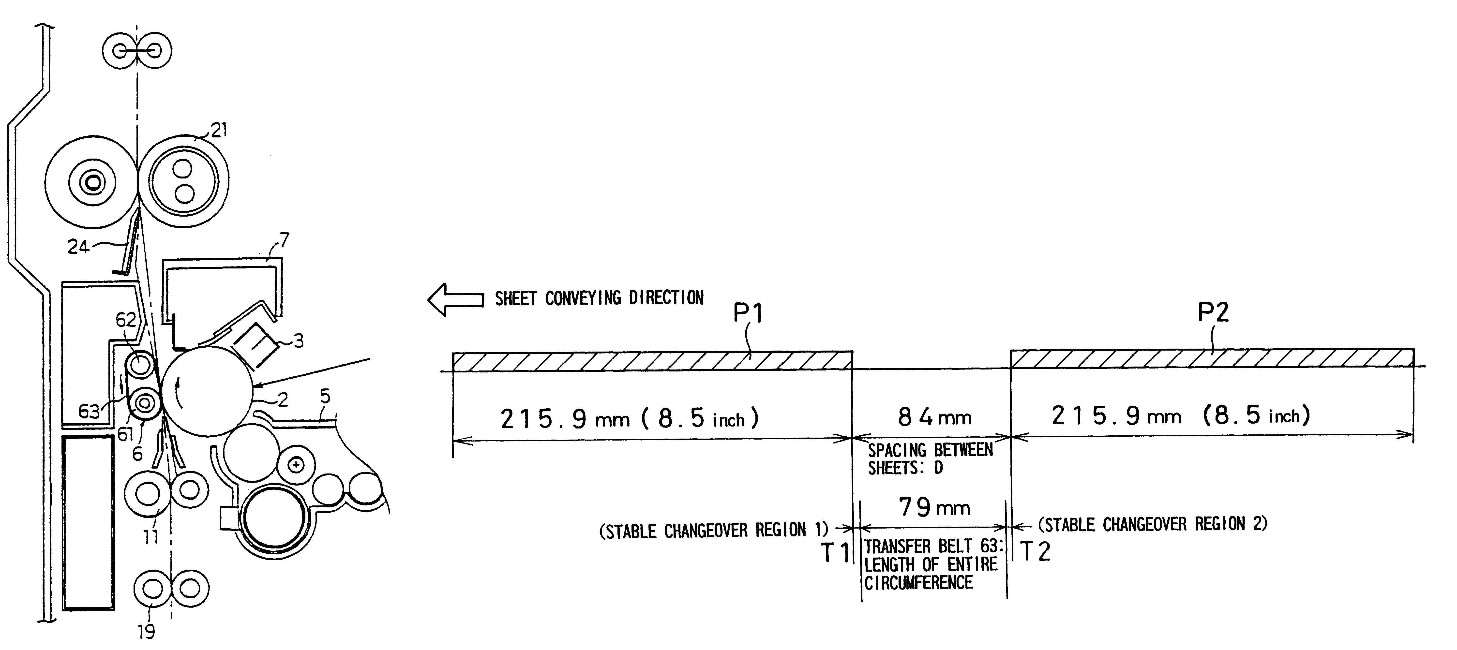
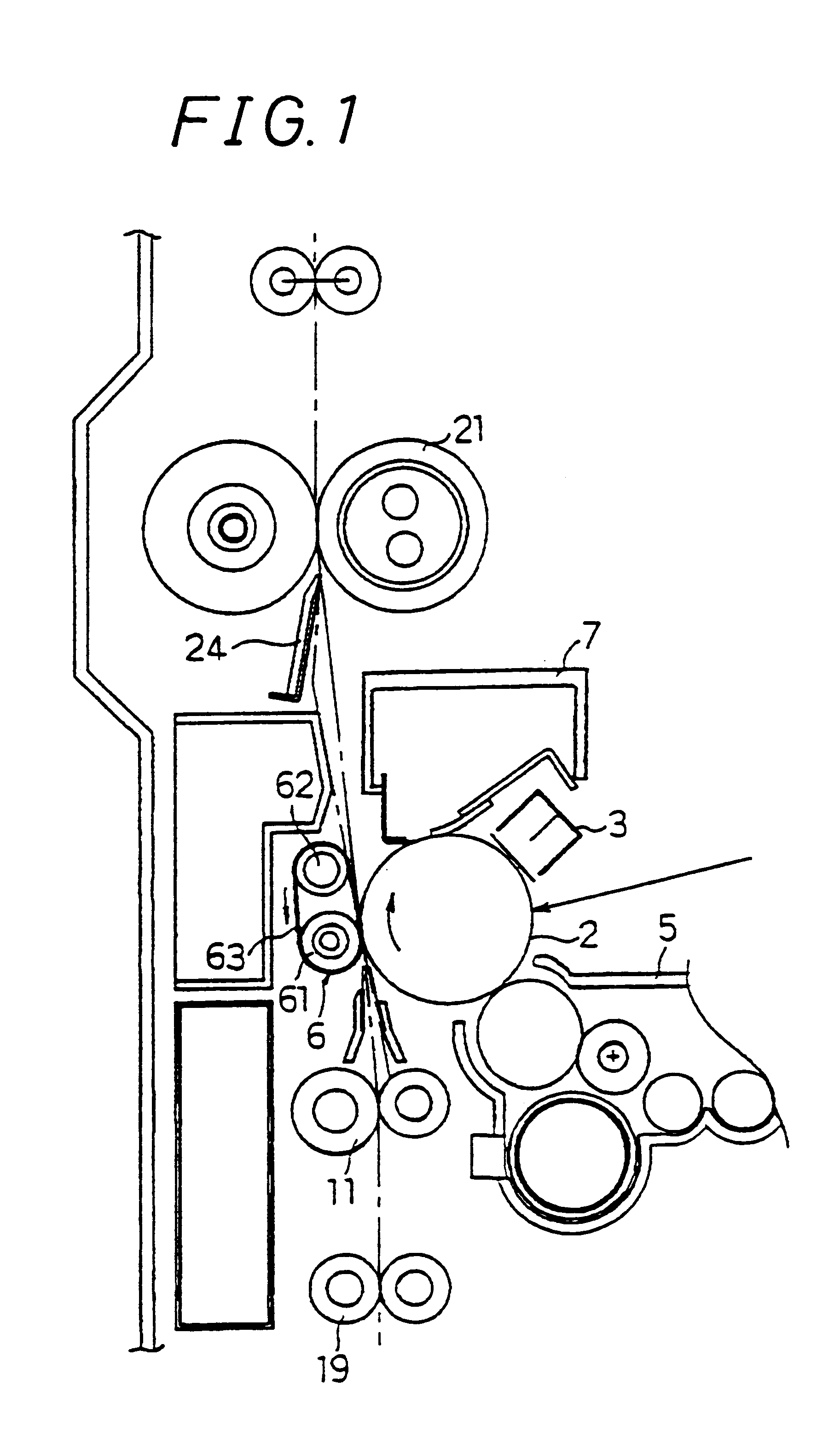
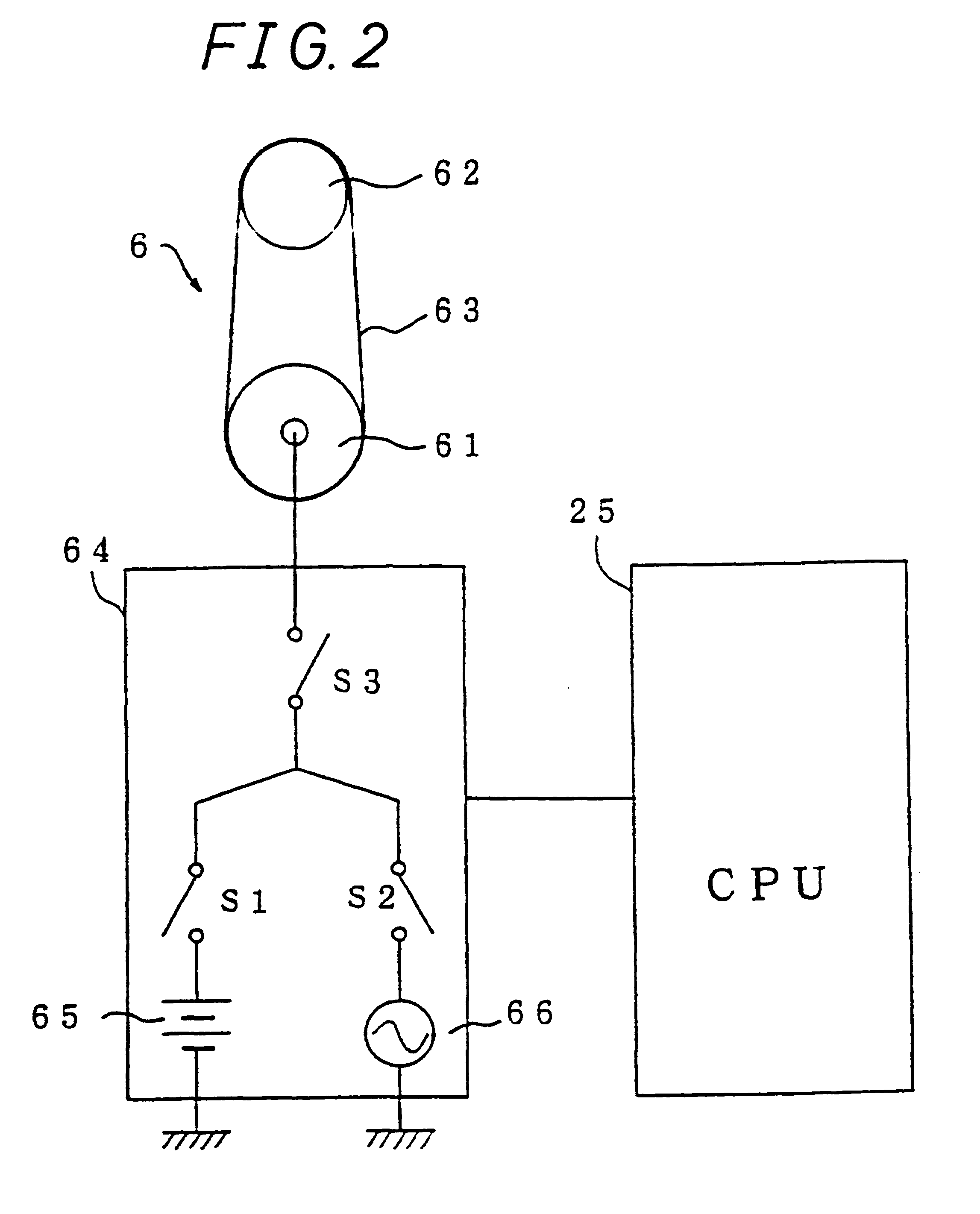
In FIG. 1 or the like, a drum-shaped photoreceptor 2 provided in an image forming apparatus 1 is set to have a diameter of 40 mm, a processing speed (output speed for image formation) of 175 mm / sec, and the entire circumferential length of a transfer belt 63 of 79 mm as shown in FIG. 3. In addition, the transfer belt 63 is formed from chloroprene (foamed body of an electrically conductive rubber), and a resistance value thereof is set to around 10.sup.11 to 10.sup.12 .OMEGA..multidot.cm.sup.3. Here, in the case where the resistance value of the transfer belt is too small, a transfer voltage would cause a current to flow to the photoreceptor 2 side through the transfer belt, thereby giving a damage to the photoreceptor 2.

Further, in the case of the use of a negative-charged toner, the transfer voltage from a DC source 65 is, for example, +2 kV, and suppl...


PUM


Abstract

It is an object of the invention to prevent reduction in output speed in the case where toner or the like adhered to a transfer belt is transferred to a side of an image carrying body and cleaning is performed by a cleaning device on a side of the image carrying body. A toner image transfer apparatus is constituted by extending a transfer belt between a first transfer roller, which is brought into pressure contact with a photoreceptor, and a second transfer roller disposed away from the photoreceptor and on a downstream side in a sheet conveying direction, and a circumferential length of the transfer belt is set to be equal to or less than a spacing between sheets conveyed (sheet spacing D) such that, in the sheet spacing D, over which a sheet passes a transfer position and which a subsequent sheet reaches, a cleaning voltage is supplied to shift toner or the like, adhered to the transfer belt, to the photoreceptor to have the same removed by a cleaning device on a side of the photoreceptor. An entire circumference of the transfer belt enables using the sheet spacing D to perform cleaning, thus ensuring a favorable cleaning quality without reduction in output speed.

Description

1. Field of the InventionThe invention relates to a toner image transfer apparatus for transferring a toner image formed on an image carrying body, to a recording material such as a sheet, in an image forming apparatus employing an electrophotographic system.2. Description of the Related ArtIn an image forming apparatus such as an image forming apparatus employing an electrophotographic system, a toner image is formed on a photoreceptor as an image carrying body and is transferred to a sheet of plain paper or the like, then the toner of the toner image is fixed on the sheet, for example, by passing the sheet through a heat fixing device, to preserve the toner image on the sheet as a permanent image on the sheet, and lastly the sheet is discharged outside the apparatus.According to such image forming apparatus, a sheet must be conveyed to a position of image formation in order to form a desired image on the sheet. For example, sheets are received in a paper feed cassette or a tray in...

Claims


Application Information

Patent Timeline
Patent Type & Authority Patents(United States)
IPC IPC(8): G03G15/16B65H5/02B65H5/00G03G21/14
CPCG03G15/168G03G15/1685G03G2215/1623G03G2215/1647G03G2215/1661
Inventor KIDA, HIROSHI
Owner SHARP KK
Why Eureka
Try Eureka