Method and liquid storage tank for minimizing permeation of liquid vapors through a tank dividing membrane

a technology of liquid vapors and dividing membranes, which is applied in the direction of gas/liquid distribution and storage, cosmonautic components, cosmonautic parts, etc., can solve the problems of gaseous pressure medium mixing with liquid fuel or oxidizer, inability to completely prevent the permeation of liquid vapors, and condensed liquid becoming trapped

Inactive Publication Date: 2001-05-15
DAMELERKLESLER AVIATION
View PDF8 Cites 27 Cited by
  • Summary
  • Abstract
  • Description
  • Claims
  • Application Information

AI Technical Summary

Problems solved by technology

However, this gives rise to the problem that the gaseous pressure medium can become mixed with the liquid fuel or oxidizer.
However, such polymeric membranes cannot completely prevent the permeation of vapors of the liquid fuel or oxidizer through the membrane and into the partial chamber containing the gaseous pressure medium.
Such a permeation process is especially caused or enhanced due to the temperature variations that are unavoidable in every technical system of this type, and the influence of these temperature variations on the differing thermal capacities of the liquid fuel or oxidizer relative to the gaseous pressure medium.
The condensed liquid then becomes trapped, so to speak, in the gas-containing partial chamber and cannot be supplied to the associated rocket engine.
Since this permeation and condensation can occur continuously, the result can be a considerable loss of useable fuel or oxidizer.
The requirements of non-permeability would essentially only be satisfied by providing metal membranes, but such metal membranes are mechanically not suitable for this application because they would suffer metal fatigue and crack formation as a result of the substantial repetitious deformation or deflection processes with a great extent of deformation, to which such dividing membranes are subjected during operation.

Method used


Image

  • Method and liquid storage tank for minimizing permeation of liquid vapors through a tank dividing membrane
  • Method and liquid storage tank for minimizing permeation of liquid vapors through a tank dividing membrane
  • Method and liquid storage tank for minimizing permeation of liquid vapors through a tank dividing membrane

Examples


Embodiment Construction

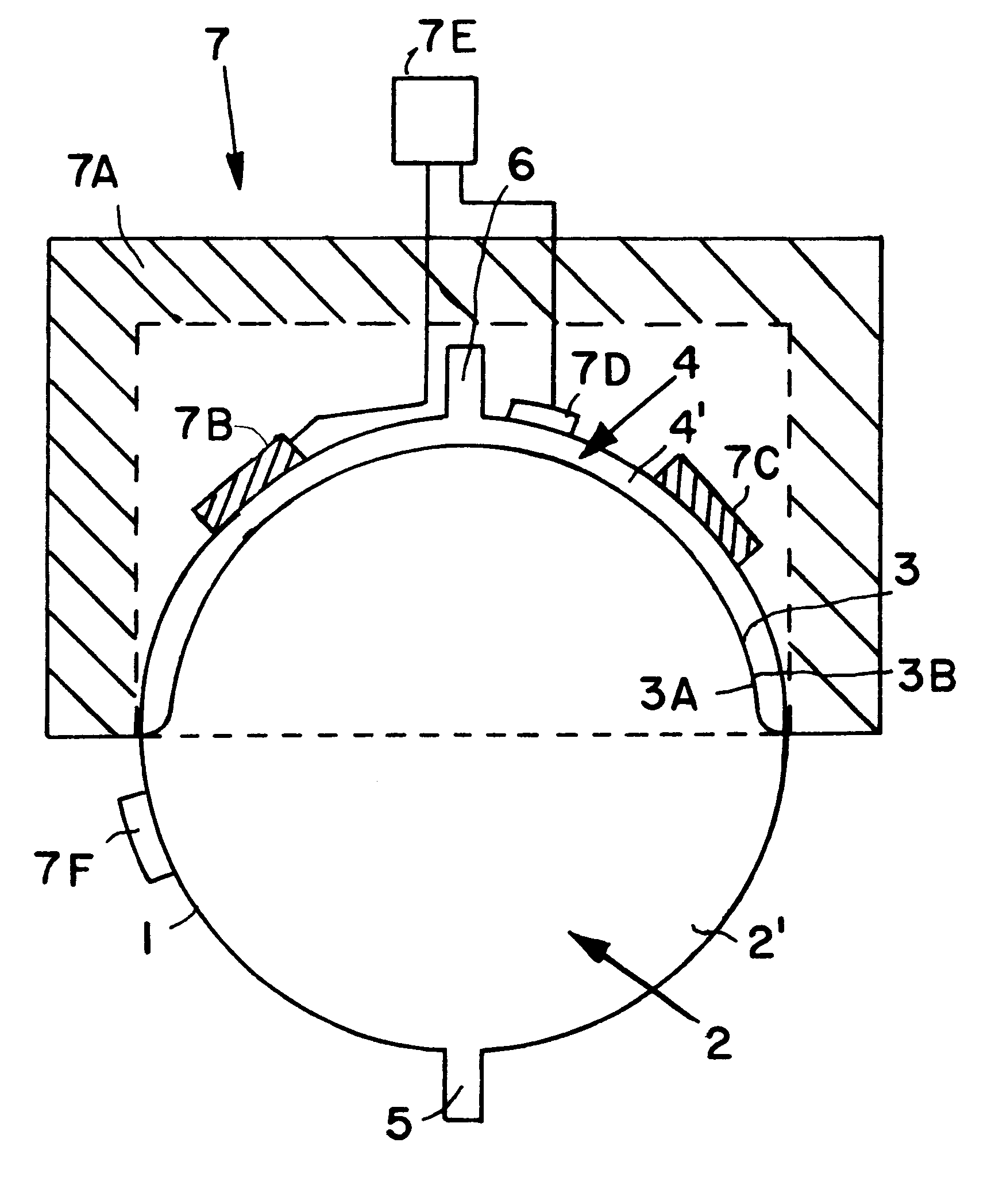
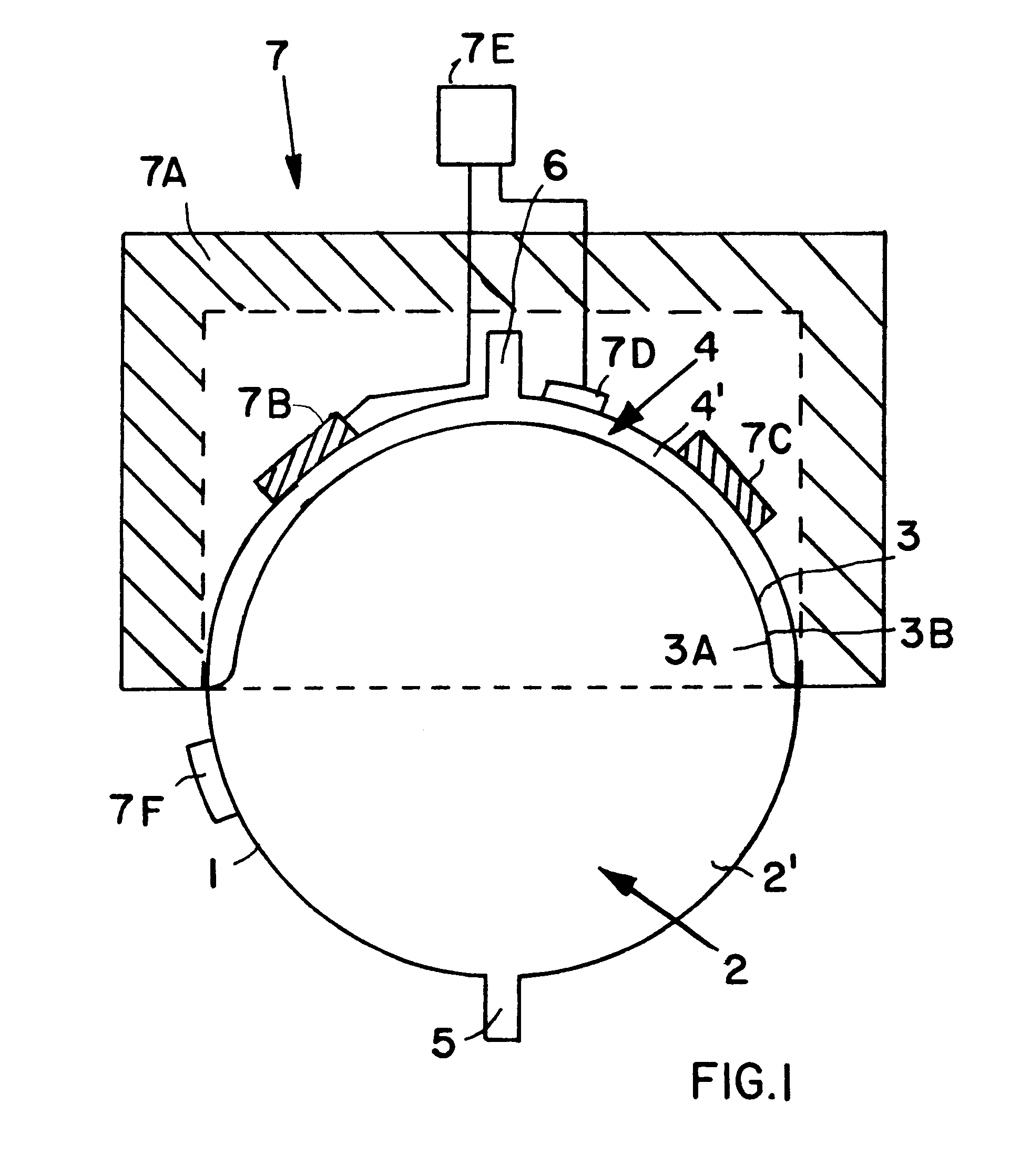
FIG. 1 is a schematic vertical section through an apparatus according to the invention, including a container or tank 1 for containing a liquid medium 2'. In the present embodiment, the container 1 is generally configured as a sphere, but it could alternatively be configured as a vertically oriented cylinder or a horizontally oriented cylinder, for example. The interior space of the container 1 is divided into a first partial chamber 2 for receiving and storing the liquid medium 2' therein, and a second partial chamber 4 for receiving a gaseous pressure medium 4' therein. This separation between the two chambers 2 and 4 is achieved by a generally semi-spherical polymeric membrane 3, which thus provides a separating barrier between the liquid medium 2' in the first chamber 2 and the gaseous pressure medium 4' in the second chamber 4.

The gaseous pressure medium 4' can be introduced into the second chamber 4 and pressurized through a gas filling pipe or pipe stub 6. The gaseous pressur...


PUM


Abstract

A temperature regulating arrangement (7) at least partially surrounds a fuel or oxidizer storage tank (1). The tank (1) is divided by a polymer membrane (3) into a first partial chamber (2) receiving the fuel (2') therein, and a second partial chamber (4) receiving a gaseous pressure medium (4') therein. The temperature regulating arrangement (7) includes thermal insulation, at least one heater, at least one heat sensor, and a temperature control and regulating unit. By heating the second partial chamber containing the gaseous pressure medium, any fuel vapor permeating through the membrane (3) from the first partial chamber (2) into the second partial chamber (4) is prevented from condensing within the second partial chamber (4). The permeation process is also limited. It is simply necessary to maintain the second partial chamber (4) at a temperature a few degrees Celsius higher than the temperature of the liquid fuel. This tank arrangement is especially suitable for use as a fuel tank or oxidizer tank in a satellite or orbital space station.

Description

PRIORITY CLAIMThis application is based on and claims the priority under 35 U.S.C. .sctn.119 of German Patent Application 198 10 638.6, filed on Mar. 12, 1998, the entire disclosure of which is incorporated herein by reference.The invention relates to a storage container or tank for storing a liquid medium and a gaseous pressure medium separated from each other, whereby the gaseous pressure medium pressurizes and causes the liquid medium to be expelled out of the tank. The invention especially relates to a tank for storing rocket fuels or oxidizers for operating the rocket engines of spacecraft, having at least one separating membrane that separates the interior space of the tank into two partial chambers.BACKGROUND INFORMATIONIn order to adjust the position and the attitude, and to stabilize the orbital motion, of satellites and orbital space stations, such orbital spacecraft typically include rocket thrusters that effectuate the required corrective movements of the spacecraft by r...

Claims


Application Information

Patent Timeline
Patent Type & Authority Patents(United States)
IPC IPC(8): B64G1/22B64G1/40F02K9/00F02K9/50F02K9/60F17C7/02F17C13/00
CPCB64G1/402F02K9/50F02K9/605
Inventor SCHWARTING, WALTER
Owner DAMELERKLESLER AVIATION
Why Eureka
Try Eureka