Eureka AIR delivers breakthrough ideas for toughest innovation challenges, trusted by R&D personnel around the world.

Oscillating air jets for reducing HSI noise

a technology of oscillating air jets and noise reduction, which is applied in the field of aerodynamic surfaces, can solve the problems of affecting and affecting the operation of both military and civilians, and achieves the effects of reducing the noise of blades and reducing the noise of hsi

Inactive Publication Date: 2001-05-22
MCDONNELL DOUGLAS
View PDF29 Cites 72 Cited by
  • Summary
  • Abstract
  • Description
  • Claims
  • Application Information

AI Technical Summary

Problems solved by technology

First, the strength of the shock wave(s) terminating the local pocket(s) of the supersonic flow on the blade affects the HSI noise.
The unsteady chordwise motion of the shock wave as a function of blade azimuth also affects the HSI noise.
The third factor contributing to HSI noise is the local airfoil geometry, such as the maximum thickness and camber constituting the tip of the rotor blade.
Regardless of the mode of operation, once strong shock waves have formed, HSI noise can severely impact the operation of both military and, to a lesser extent, commercial rotorcraft.
No active noise control techniques are known for reducing the strength of the shock waves responsible for HSI noise.
Conventional methods, although partially effective, do not guarantee low HSI noise levels at operation conditions other than the specifically designed and engineered operation condition.

Method used


Image

  • Oscillating air jets for reducing HSI noise
  • Oscillating air jets for reducing HSI noise
  • Oscillating air jets for reducing HSI noise

Examples


Embodiment Construction

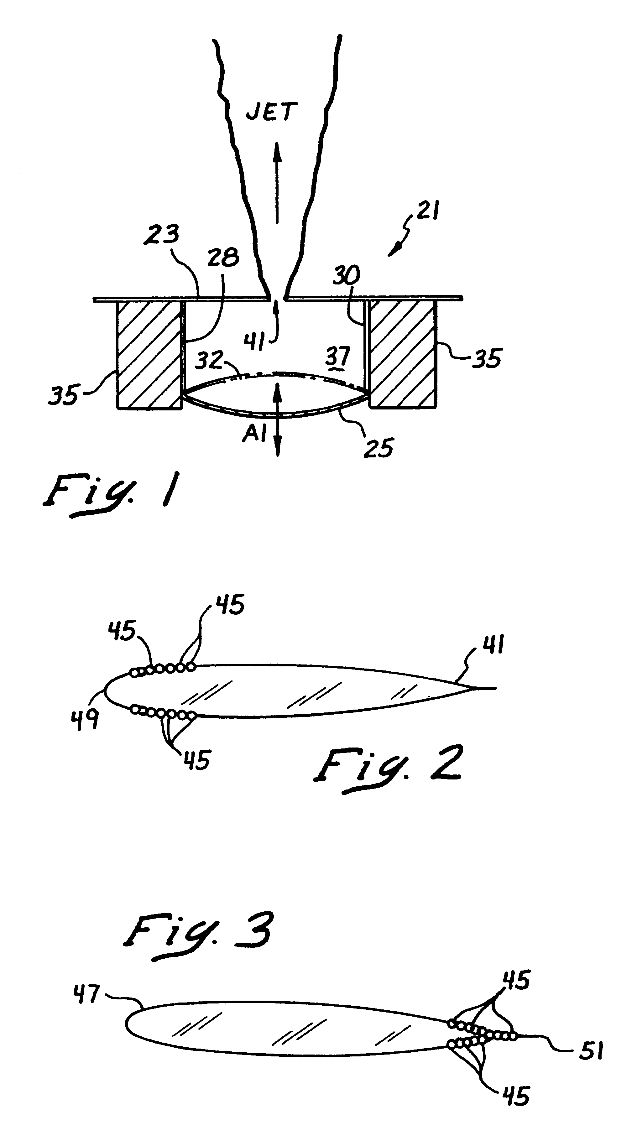
Referring now more particularly to the drawings, FIG. 1 illustrates an oscillating air jet assembly 21 which is disposed on an aerodynamic surface 23. The oscillating airjet 21 comprises a diaphragm 25 formed of a piezoelectric material. The diaphragm 25 is preferably supported between a first conductor 28 and a second conductor 30, and is movable in the directions of the arrows A1 between a first position indicated by the reference numeral 25 and a second position indicated by the phantom lines 32.

A chassis 35 secures the first conductor 28 and the second conductor 30 to the aerodynamic surface 23. An oscillating current is provided to the diaphragm 25 via the first conductor 28 and the second conductor 30, to thereby electrically stimulate the diaphragm 25 to oscillate in directions of the arrows A1.

Movement of the diaphragm from a first position 25 to a position 32 shown in phantom produces a positive pressure within the sealed chamber 37, and movement of the diaphragm in the opp...


PUM


Abstract

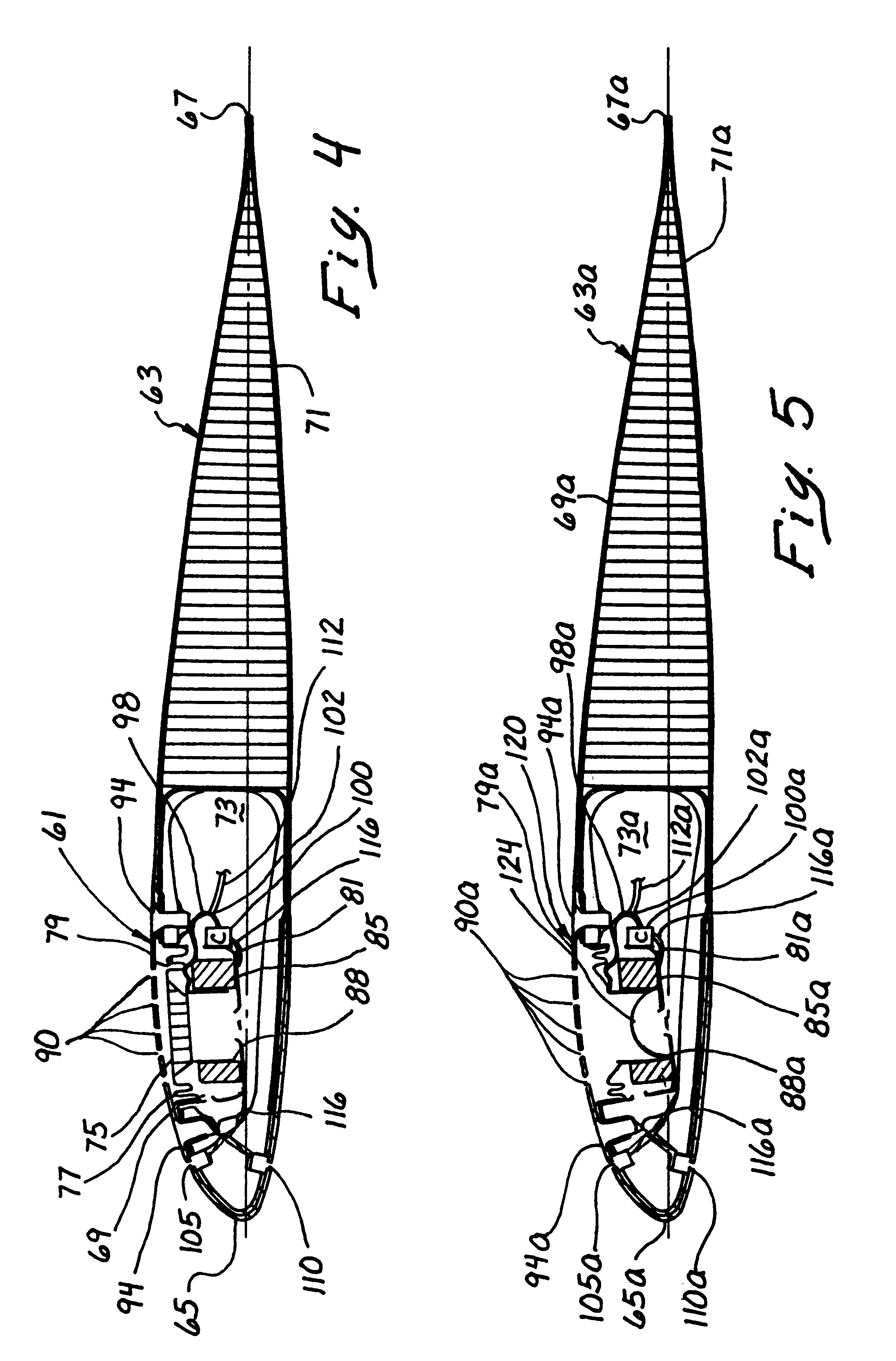
Porous surfaces on an aerodynamic structure driven with positive and negative pressures are used in an active control system for attenuating shock waves responsible for high-speed impulsive (HSI) noise. The control system includes an array of apertures in the outer skin of the structure providing fluid communication between the exterior flow stream and an interior volume of the structure. A movable diaphragm within the structure pushes air out of and pulls air in through the apertures under the action of a drive mechanism within the structure, thus creating oscillating air jets. The drive mechanism may be actuated by a controller based on information supplied by a sensor in the leading edge of the aerodynamic structure. The array of apertures may be spaced apart along the outer skin of the aerodynamic structure so as to span a distance of about 15% of the chord length. The oscillating airjets may be provided on multiple surfaces of the aerodynamic structure, including the upper and lower surfaces.

Description

1. Field of the InventionThis invention relates generally to aerodynamic surfaces and, more particularly, to improved constructions and control schemes for such aerodynamic surfaces which provide for aerodynamic control and for significant reductions in noise in the case of rotor blades.2. Description of Related ArtCommercial and military helicopters / tiltrotors in hover and in high-speed forward (or edgewise) flight generate an impulsive noise signature which is commonly referred to as high-speed impulsive (HSI) noise. Three factors are known to affect the intensity of HSI noise. First, the strength of the shock wave(s) terminating the local pocket(s) of the supersonic flow on the blade affects the HSI noise. The unsteady chordwise motion of the shock wave as a function of blade azimuth also affects the HSI noise. The third factor contributing to HSI noise is the local airfoil geometry, such as the maximum thickness and camber constituting the tip of the rotor blade. The local airfo...

Claims


Application Information

Patent Timeline
Patent Type & Authority Patents(United States)
IPC IPC(8): B64C27/32B64C23/04B64C27/467B64C23/00B64C27/51B64C27/00
CPCB64C23/04B64C27/001B64C27/467B64C27/51B64C2027/725Y02T50/166Y02T50/34B64C2230/02B64C2230/06Y10S416/50B64C2230/14B64C2230/22B64C2230/18B64C2230/28Y02T50/10Y02T50/30
Inventor HASSAN, AHMED A.TADGHIGHI, HORMOZJANAKIRAM, RAM D.
Owner MCDONNELL DOUGLAS
Why Eureka
Eureka Blog
Learn More