
Fuel assembly spacer grid with swirl deflectors and hydraulic pressure springs

a technology of swirl deflectors and fuel assembly spacers, which is applied in nuclear elements, greenhouse gas reduction, nuclear engineering, etc., can solve the problems of fuel elements being subjected to fretting wear, fuel elements vibrating, and fuel elements being reduced in the support force of the springs for fuel elements, so as to reduce the initial mechanical spring force, reduce the loss of pressure in the cooling water flow, and suppress the effect of fuel element vibration

Inactive Publication Date: 2001-05-22
KOREA HYDRO & NUCLEAR POWER CO LTD +1
View PDF27 Cites 62 Cited by
  • Summary
  • Abstract
  • Description
  • Claims
  • Application Information

AI Technical Summary

Benefits of technology

Another object of the invention is to provide a fuel assembly spacer grid provided with swirl deflectors each capable of generating a strong swirling flow of cooling water while using a small bent angle at which the swirl deflector comes into contact with the cooling water, thereby minimizing the loss of pressure in the cooling water flow caused by the provision of the swirl deflector.
Another object of the invention is to provide a fuel assembly spacer grid capable of utilizing the hydraulic drag force on spring in a cooling water flow passing through the spacer grid as an additional spring force, thereby compensating for a decrease in the initial mechanical spring force caused by a change in the property of the material of the spacer grid occurring in a reactor core where the spacer grid is disposed.
Another object of the invention is to provide a fuel assembly spacer grid in which the portions of the springs and dimples thereof contacting fuel elements have a conformal surface contact shape in such a manner that those contact portions are in surface contact with the fuel elements, thereby effectively suppressing vibrations of the fuel elements and greatly reducing the possibility of a fretting abrasion of the fuel elements resulting in a damage of the fuel elements.

Problems solved by technology

This results in a reduction in the support force of the springs for the fuel elements, thereby causing those elements to vibrate.
Due to such vibrations, the fuel elements may be subjected to a fretting wear at portions contacting the fuel element-supporting elements of the straps.
Such a fretting wear of the fuel elements results in a perforation of the fuel elements which, in turn, causes a leakage of radioactivity.
In the case of springs in which elasticity depends only on a material used, as in the above mentioned springs, a reduction in elasticity occurs inevitably due to an irradiation of neutrons onto the springs.
However, an increase in the initial spring force may result in an increase in the force required upon initially placing a nuclear fuel assembly, thereby causing a damage of fuel elements.
On the other hand, fuel elements placed in a reactor core exhibit a non-uniform heat flux distribution.
Due to such a non-uniform heat flux distribution, a severe increase in the temperature of a cooling water in the reactor core occurs at areas surrounding fuel elements generating a higher heat flux, namely, exhibiting a higher temperature.
Where the formation of such bubbles may become severe, thereby covering the surfaces of fuel elements, an abrupt degradation in heat transfer efficiency occurs.
This results in an abrupt increase in temperature on the surface of fuel elements.
In such a method, however, the flow mixing function is greatly attenuated as the cooling water flows downstream away from the spacer grid.
The provision of a flow mixer results in an additional pressure loss because an increase in the projected area causes a reduction in the area through which the cooling water flows.
Such an increase in pressure loss results in an increase in the load applied to a pump for pumping the cooling water.
For this reason, there is a problem in that the flow rate of the cooling water flowing in the nuclear reactor decreases.
In this case, a severe heat flux peaking phenomenon may occur.
This results in a high possibility of a great degradation in heat transfer rate.

Method used


Image

  • Fuel assembly spacer grid with swirl deflectors and hydraulic pressure springs
  • Fuel assembly spacer grid with swirl deflectors and hydraulic pressure springs
  • Fuel assembly spacer grid with swirl deflectors and hydraulic pressure springs

Examples


Embodiment Construction

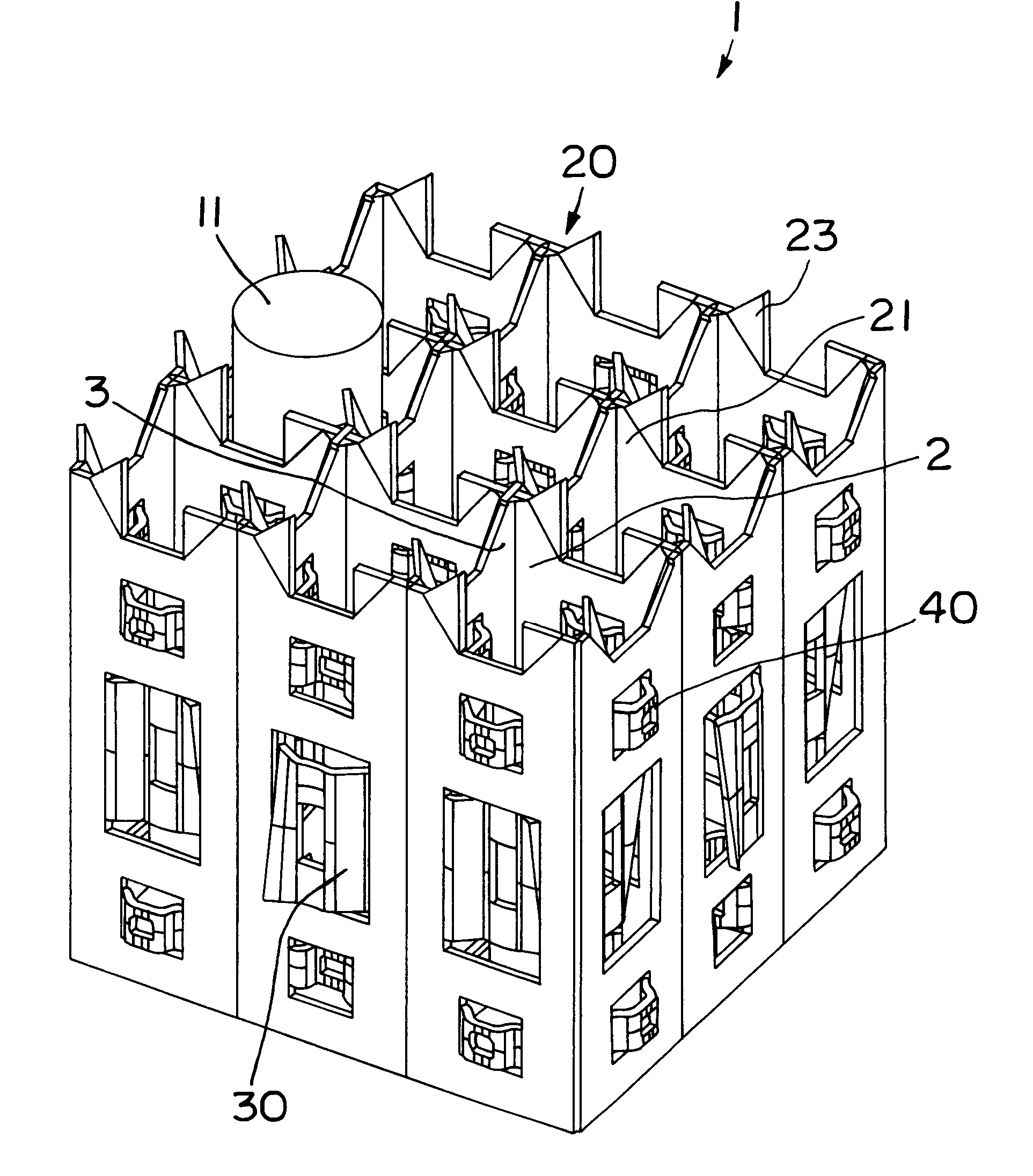
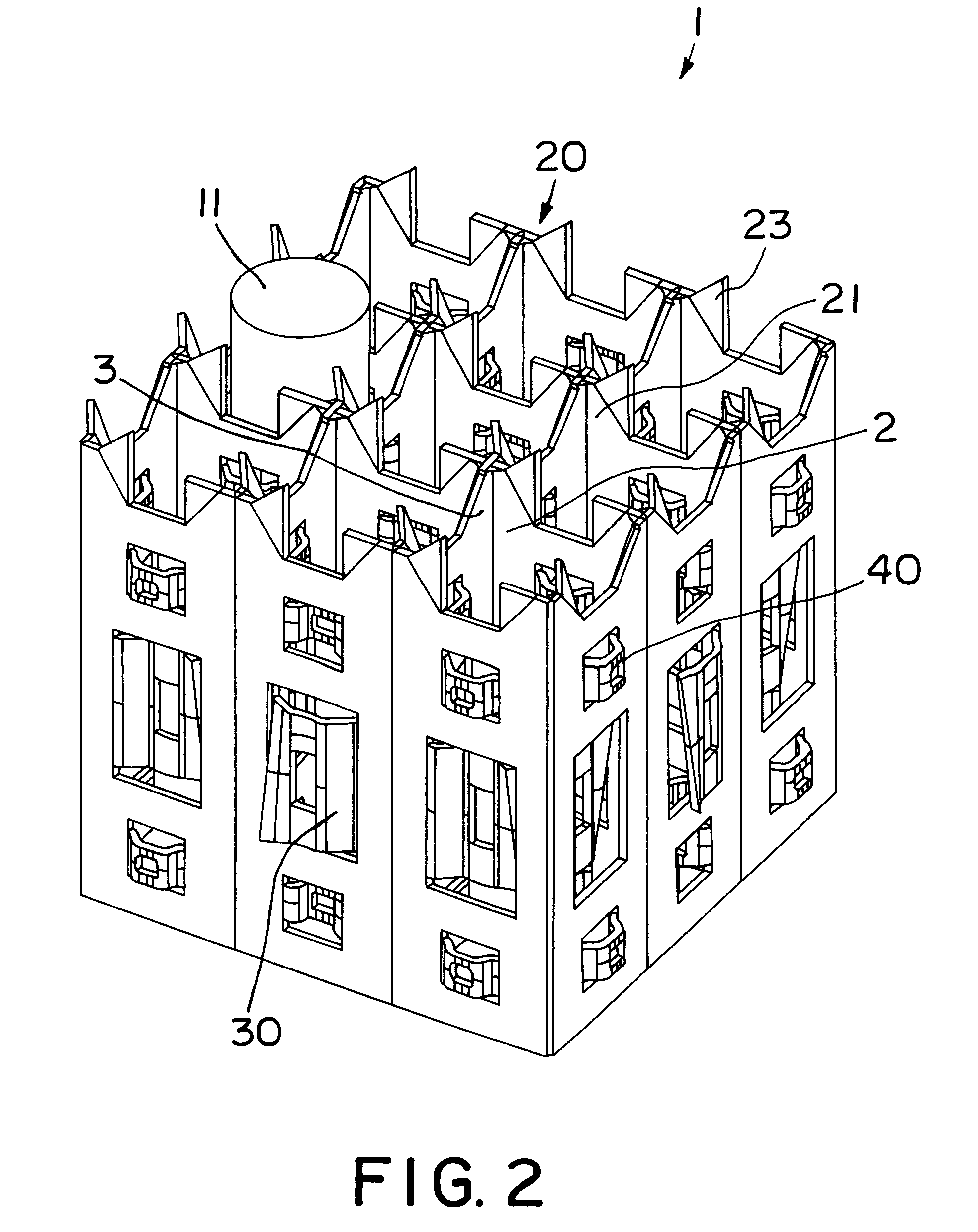
Referring to FIG. 2, a fuel assembly spacer grid according to an embodiment of the present invention is illustrated. As shown in FIG. 2, the spacer grid, which is denoted by the reference numeral 1, includes a plurality of longitudinally-extending, parallel, spaced vertical straps 2 and a plurality of laterally-extending, parallel, spaced vertical straps 3 perpendicularly interconnecting the longitudinally-extending straps 2, in order to support fuel elements of a nuclear fuel assembly. The spacer grid 1 also includes a plurality of swirl deflectors 20 respectively provided at the upper ends of the interconnections between the straps 2 and 3, a plurality of springs 30 provided at the straps 2 and 3, and a plurality of dimples 40 provided at the straps 2 and 3. As shown in FIG. 3 viewing the spacer grid 1 from above, the springs 30 and dimples 40 have conformal contact portions having the same radius of curvature as fuel elements 11 to be supported by the spacer grid 1. The swirl def...


PUM


Abstract

A fuel assembly spacer grid including swirl deflectors respectively arranged at interconnections between interconnecting longitudinally and laterally-extending straps on upper ends of the interconnecting straps adapted to support fuel elements of a nuclear fuel assembly. Each of the swirl deflectors has four vanes bent to have an air vane shape. By virtue of this configuration, an improvement in the efficiency of the spacer grid cooling the fuel elements. The spacer grid also includes springs each configured to generate not only a main spring force caused by a displacement of the spring occurring when the spring comes into contact with a fuel element placed in a reactor core, but also an additional spring force caused by hydraulic pressure applied to the spring. Each spring, which is in a fixed state at one end thereof, has a free bent portion at the other end. By virtue of such a spring configuration, it is possible to compensate for a reduction in the initial spring force of the spring resulting from a change in the property of the spring material. The spring has a curved contact portion configured in such a manner that it is in conformal surface contact with a circumferential surface of the fuel element, thereby enhancing vibration suppressing and abrasion resistance forces.

Description

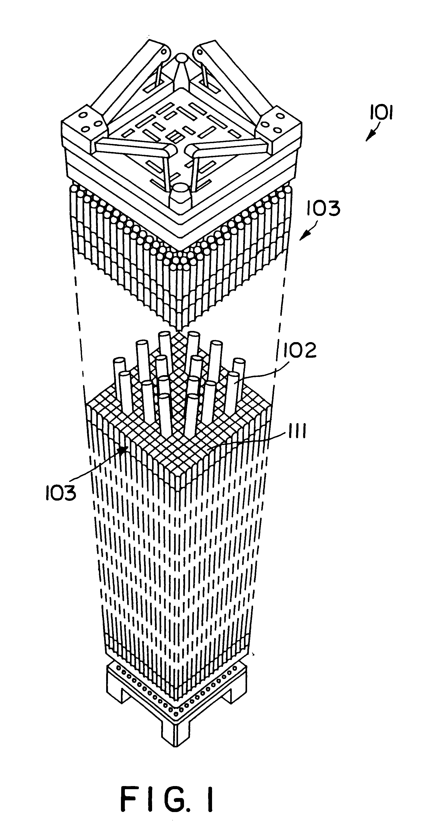
BACKGROUND OF THE INVENTION1. Field of the InventionThe present invention relates to a fuel assembly spacer grid for nuclear reactors, and more particularly to a fuel assembly spacer grid used for a nuclear fuel assembly placed in a reactor core at a nuclear power plant, which spacer grid is provided with swirl deflectors, hydraulic pressure springs, and wear resistant springs.2. Description of the Prior ArtReferring to FIG. 1, a nuclear reactor is illustrated in which a nuclear fuel assembly is placed in a reactor core denoted by the reference numeral 101. Typically, a spacer grid 103 is used to firmly support fuel elements 111 of the nuclear fuel assembly in a state placed in the reactor core. Such a spacer grid 103 consists of a plurality of longitudinally-extending parallel vertical straps and a plurality of laterally-extending parallel vertical straps perpendicularly interconnecting the longitudinally-extending straps. The fuel elements 111 are placed in internal spaces defined...

Claims


Application Information

Patent Timeline
IPC IPC(8): G21C3/322G21C3/32G21C3/34
CPCG21C3/322G21C2003/3432Y02E30/38G21C3/3432Y02E30/30G21C3/34
Inventor CHUN, TAE-HYUNOH, DONG-SEOKIN, WANG-KEESONG, KEE-NAMKANG, HEUNG-SEOKYOON, KYUNG-HOKIM, DAE-HOBANG, JE-GEONJUNG, YOUN-HO
Owner KOREA HYDRO & NUCLEAR POWER CO LTD
Learn More