Thin film forming apparatus and method of forming thin film of compound by using the same

a technology of thin film and forming apparatus, which is applied in the direction of instruments, optical elements, vacuum evaporation coating, etc., can solve the problems of insufficient inability to achieve sufficient sputtering rate or film characteristics, and inability to achieve the improvement of a sufficient sputtering rate or the effect of film quality

Inactive Publication Date: 2001-05-29
CANON KK
View PDF14 Cites 66 Cited by
  • Summary
  • Abstract
  • Description
  • Claims
  • Application Information

AI Technical Summary

Problems solved by technology

When the flow rate of a reaction gas decreases in the case of a metal target, a formed thin film of a metallic compound has a large content of metal atoms, whereby the formed film cannot satisfy a stoichiometric ratio thereof and is inferior in its optical characteristics (refractive index, transmittance, etc.) and so on.
Therefore, improvement of a film quality and increase of a sputtering rate cannot be expected.
Accordingly, improvement of a sufficient sputtering rate or film characteristics cannot be as expected.
Further, this apparatus requires prelimi...

Method used


Image

  • Thin film forming apparatus and method of forming thin film of compound by using the same
  • Thin film forming apparatus and method of forming thin film of compound by using the same
  • Thin film forming apparatus and method of forming thin film of compound by using the same

Examples


Embodiment Construction

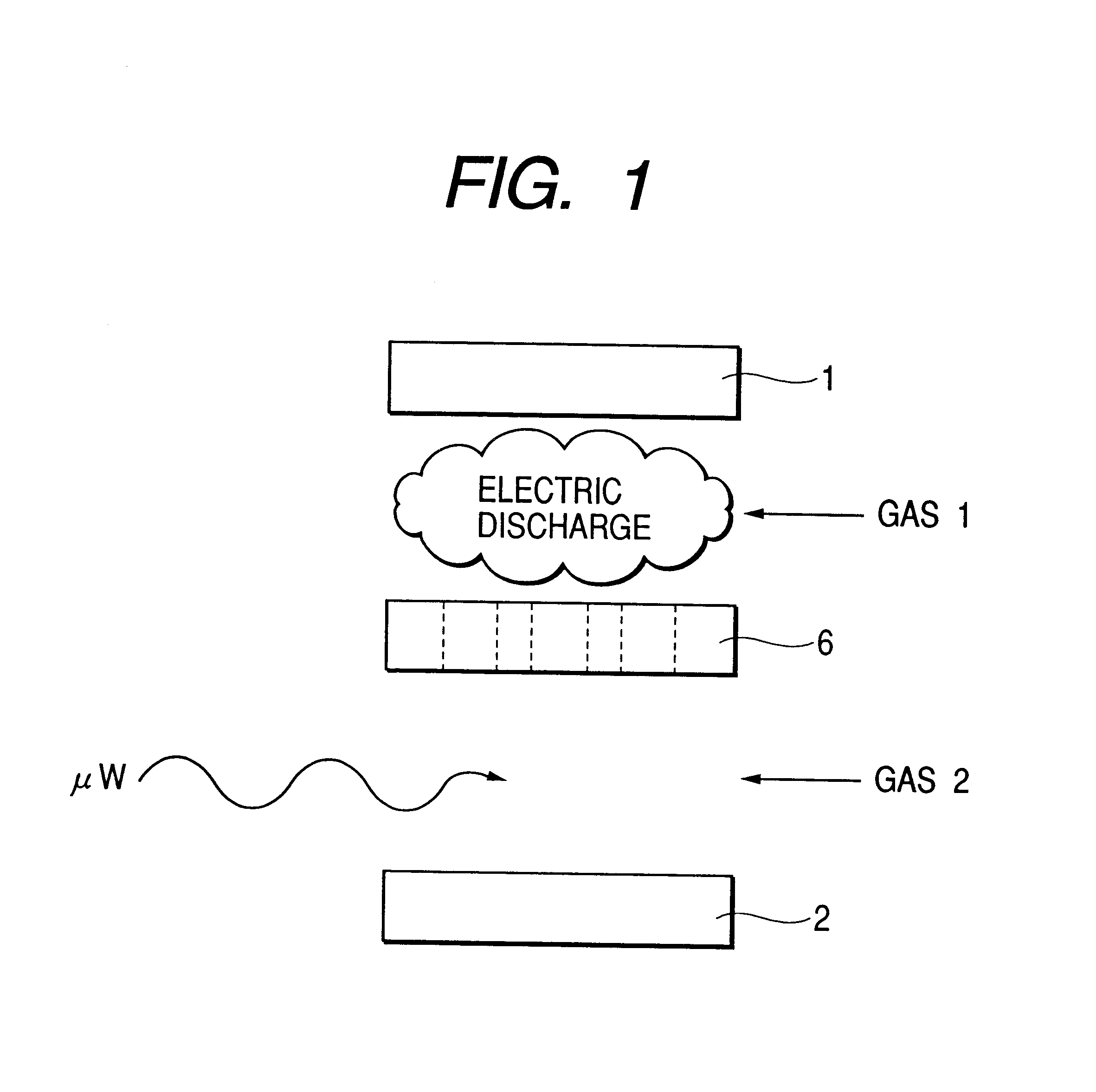
FIG. 1 is a schematic diagram for explaining a fundamental embodiment of the present invention.

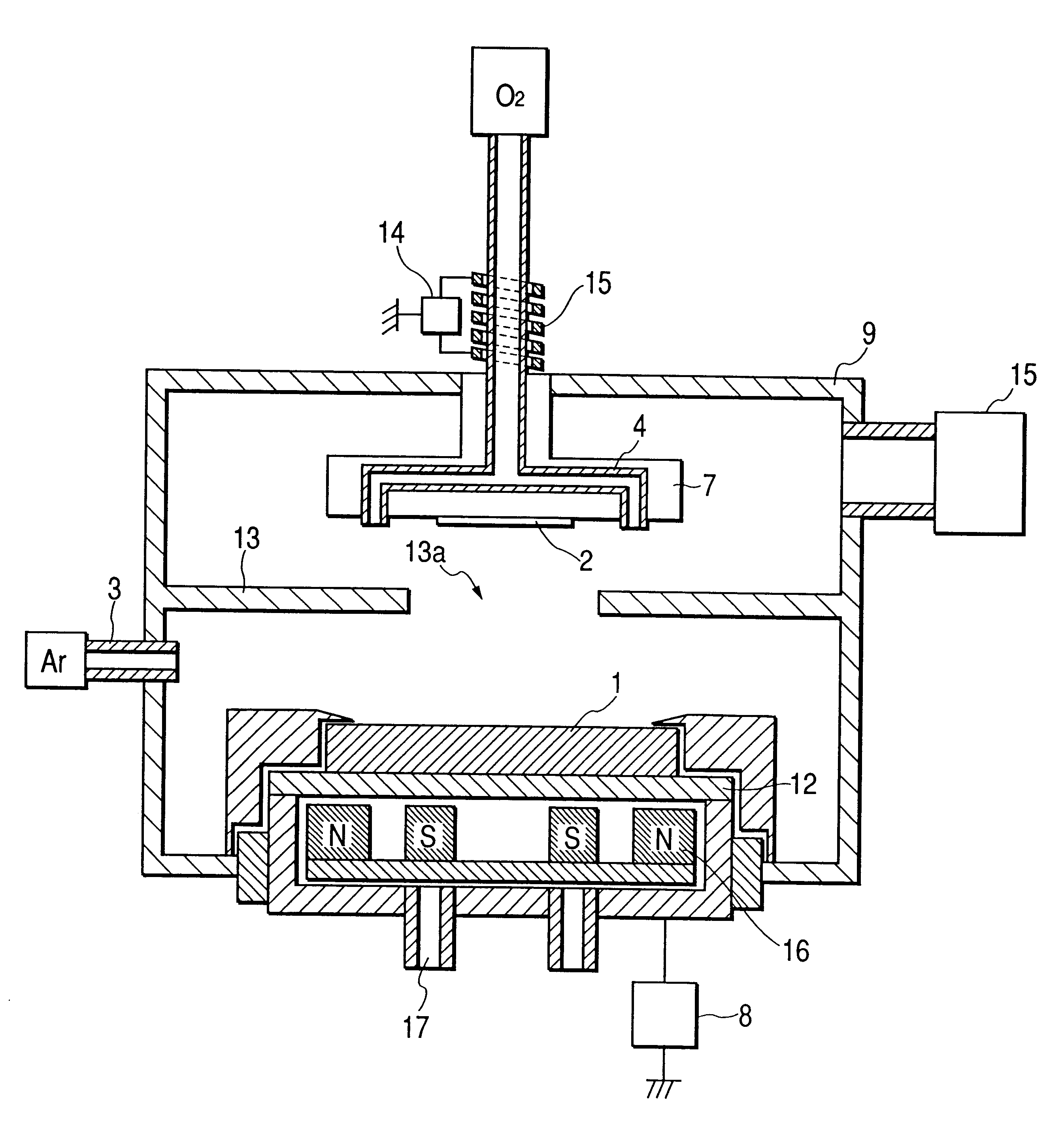
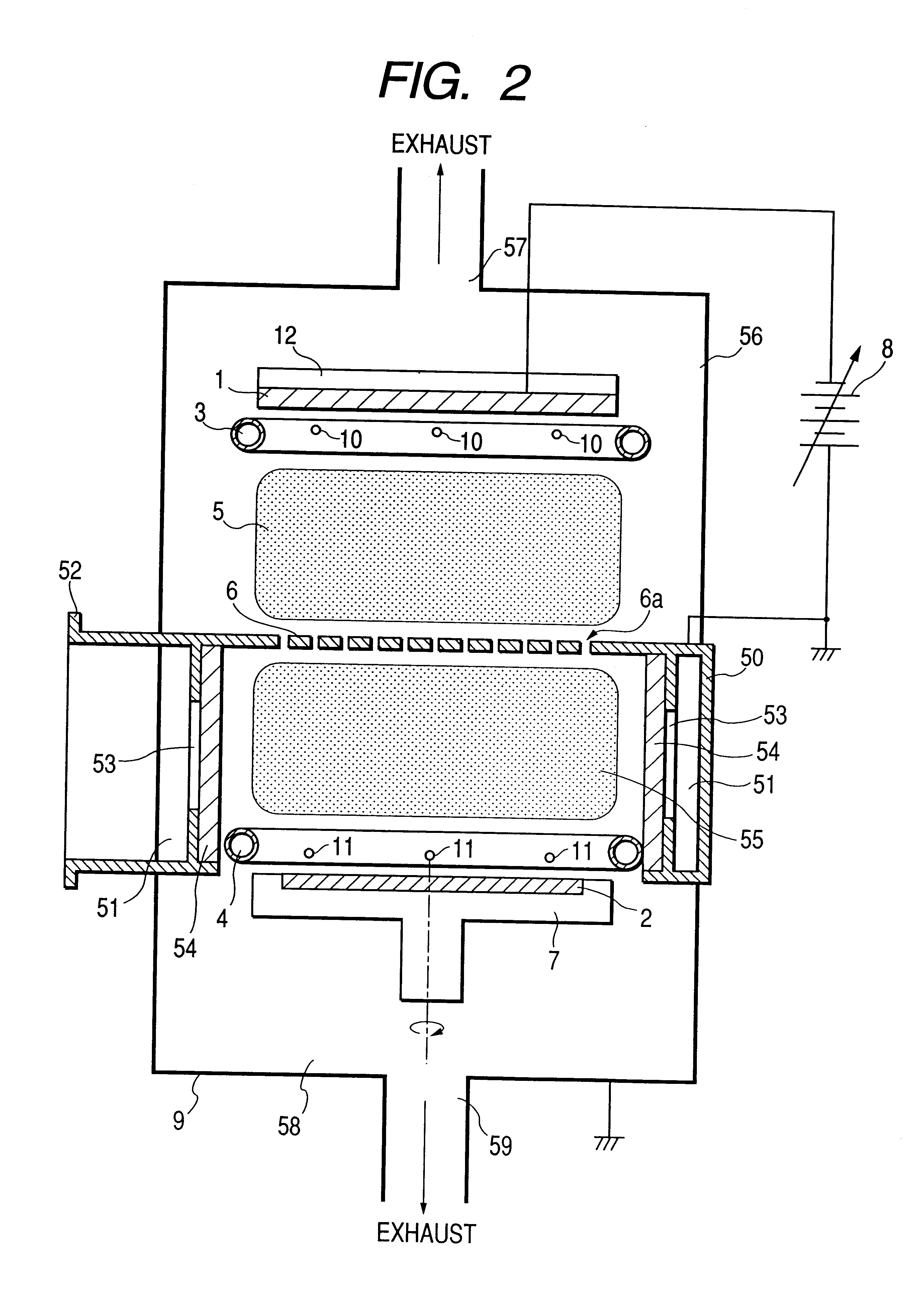
A reference numeral 1 indicates a raw material used as a sputtering target, 2 a substrate on which a film is to be formed, and 6 a partition member.

A sputtering gas GAS1 is supplied into a space between the raw material 1 and the partition member 6. The sputtering gas GAS1 causes an electric discharge in the space with an electric energy, thereby sputtering the raw material 1.

Particles produced by the sputtering pass through openings formed in the partition member 6, and reach a space between the partition member 6 and the substrate 2.

Since a reaction gas GAS2 is supplied into this space, the sputtered particles of the raw material react with the reaction gas in the vicinity of the substrate 2 or on a surface of the substrate 2.

Since a microwave is supplied into the space on the side of the substrate 2, the reaction gas is ionized and / or activated by an energy of the microwave, thereby str...


PUM

PropertyMeasurementUnit
Poweraaaaaaaaaa
Electric propertiesaaaaaaaaaa
Lightaaaaaaaaaa

Abstract

A film forming apparatus for forming a minute thin film at a high depositing rate, which comprises a substrate holding means for holding a substrate, a target holding means for holding a target, a gas supply means for supplying a sputtering gas for sputtering the target into a reaction chamber, and an electric power supply means for supplying an electric power for causing an electric discharge between the target and the substrate, wherein a partition member having a plurality of openings provided between the target and the substrate, and wherein means for supplying a reaction gas and a microwave are provided in a space between the partition member and the substrate.

Description

1. Field of the InventionThe present invention relates to a thin film forming apparatus and more specifically a thin film forming method suitable for forming electrodes and protective films for semiconductor devices, electrodes and protective films for liquid crystal apparatus, protective films for photomagnetic recording media, and antireflective films and reflection enhancing films for optical articles.2. Related Background ArtSputtering is known as one of thin film forming methods.In a conventional reactive sputtering, a gas mixture of a sputtering gas and a reaction gas is introduced into a reaction chamber, and a compound target or a metal target is sputtered to form a thin film of a metal compound by a chemical reaction between atoms constituting a target and a reaction gas. A depositing rate is generally low for an insulating compound target, though electric discharge can be caused by supplying a high-frequency electric power such as of RF or microwave. For a metal target, it...

Claims


Application Information

Patent Timeline
IPC IPC(8): C23C14/00H01J37/32H01J37/34G02B1/10
CPCC23C14/0047C23C14/0068H01J37/32192H01J37/3405G02B1/10C23C14/34
Inventor SONE, KAZUHOSUZUKI, NOBUMASA
Owner CANON KK
Why Eureka
Try Eureka