
Object position detection system and method

a technology of object position and detection system, applied in the field of object position recognition, can solve the problems of large size, high cost of trackball devices, and inability to detect objects,

Inactive Publication Date: 2001-05-29
SYNAPTICS INC
View PDF184 Cites 418 Cited by
  • Summary
  • Abstract
  • Description
  • Claims
  • Application Information

AI Technical Summary

Benefits of technology

It is a further object of the present invention to provide a two-dimensional capacitive sensing system wherein all row electrodes are sensed simultaneously, and all column electrodes are sensed simultaneously and wherein digital electronic processing is employed efficiently to define the location of a finger or other conductive object.
According to yet another aspect of the present invention, a capacitance measurement technique which is easier to calibrate and implement is employed.

Problems solved by technology

Finally, a mouse requires the user to lift a hand from the keyboard to make the cursor movement, thereby upsetting the prime purpose, which is usually typing on the computer.
Trackball devices are still expensive, have moving parts, and require a relatively heavy touch as do the mouse devices.
They are also large in size and doe not fit well in a volume-sensitive application like a laptop computer.
However, they generally suffer from poor resolution, the sensor surface is exposed to the user and is thus subject to wear.
In addition, resistive-membrane touch sensors are relatively expensive.
This cannot be guaranteed in portable computers.
A two-surface approach has poorer resolution and potentially will wear out very quickly in time.
The drawback of all such approaches is the high power consumption and the high cost of the resistive membrane employed.
However, this sensor technology is expensive and is not sensitive to light touch.
In addition, SAW devices are sensitive to residue buildup on the touch surfaces and generally have poor resolution.
Strain gauge or pressure plate approaches are an interesting position sensing technology, but suffer from several drawbacks.
One drawback is that the piezo phenomena is an AC phenomena and may be sensitive to the user's rate of movement.
In addition, strain gauge or pressure plate approaches are somewhat expensive because special sensors are required.
Optical approaches are also possible but are somewhat limited for several reasons.
All would require light generation which will require external components and increase cost and power drain.
For example, a "finger-breaking" infra-red matrix position detector consumes high power and suffers from relatively poor resolution.
Because the method relies on synchronous detection of the exciting signal, it must average for long periods to reject electrical interference, and hence it is slow.
The averaging time required by this method, together with the necessity to search sequentially for a new finger contact once a previous contact is lost, makes this method, like those before it, fall short of the requirements for a fast pointing device that is not affected by electrical interference.
Greanias and Evans use a complicated and expensive drive, sense and electrode line scheme to develop their signal.
The sequential scanning approach of previous systems also made them more susceptible to noise.
Because the transfer curve is very sensitive to many parameters and is not a smooth linear curve as Greanias and Gerpheide assume, such approaches are limited in the amount of interpolation they can perform.

Method used


Image

  • Object position detection system and method
  • Object position detection system and method
  • Object position detection system and method

Examples


Embodiment Construction

This application is a continuation-in-part of co-pending application Ser. No. 08 / 115,743, filed Aug. 31, 1993, now U.S. Pat. No. 5,374,787, which is a continuation-in-part of co-pending application Ser. No. 07 / 895,934, filed Jun. 8, 1992. The present invention continues the approach disclosed in the parent applications and provides more unique features not previously available. These improvements provide a more easily integrated solution, increased sensitivity, and greater noise rejection, increased data acquisition rate and decreased power consumption. Additionally, the present invention allows for continuous self calibration to subtract out the effects of environmental changes.

Those of ordinary skill in the art will realize that the following description of the present invention is illustrative only and not in any way limiting. Other embodiments of the invention will readily suggest themselves to such skilled persons.

The present invention brings together in combination a number of...


PUM


Abstract

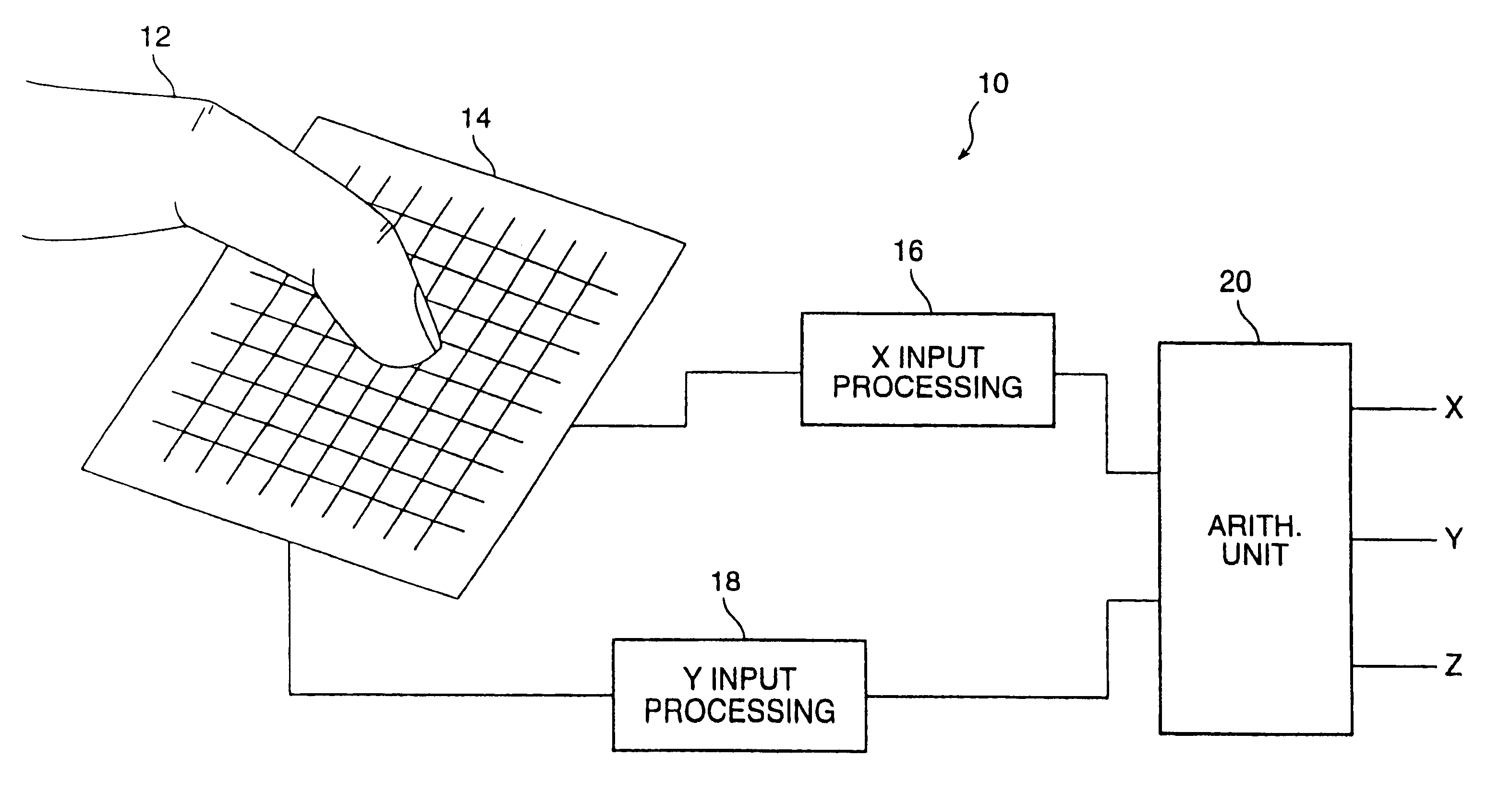
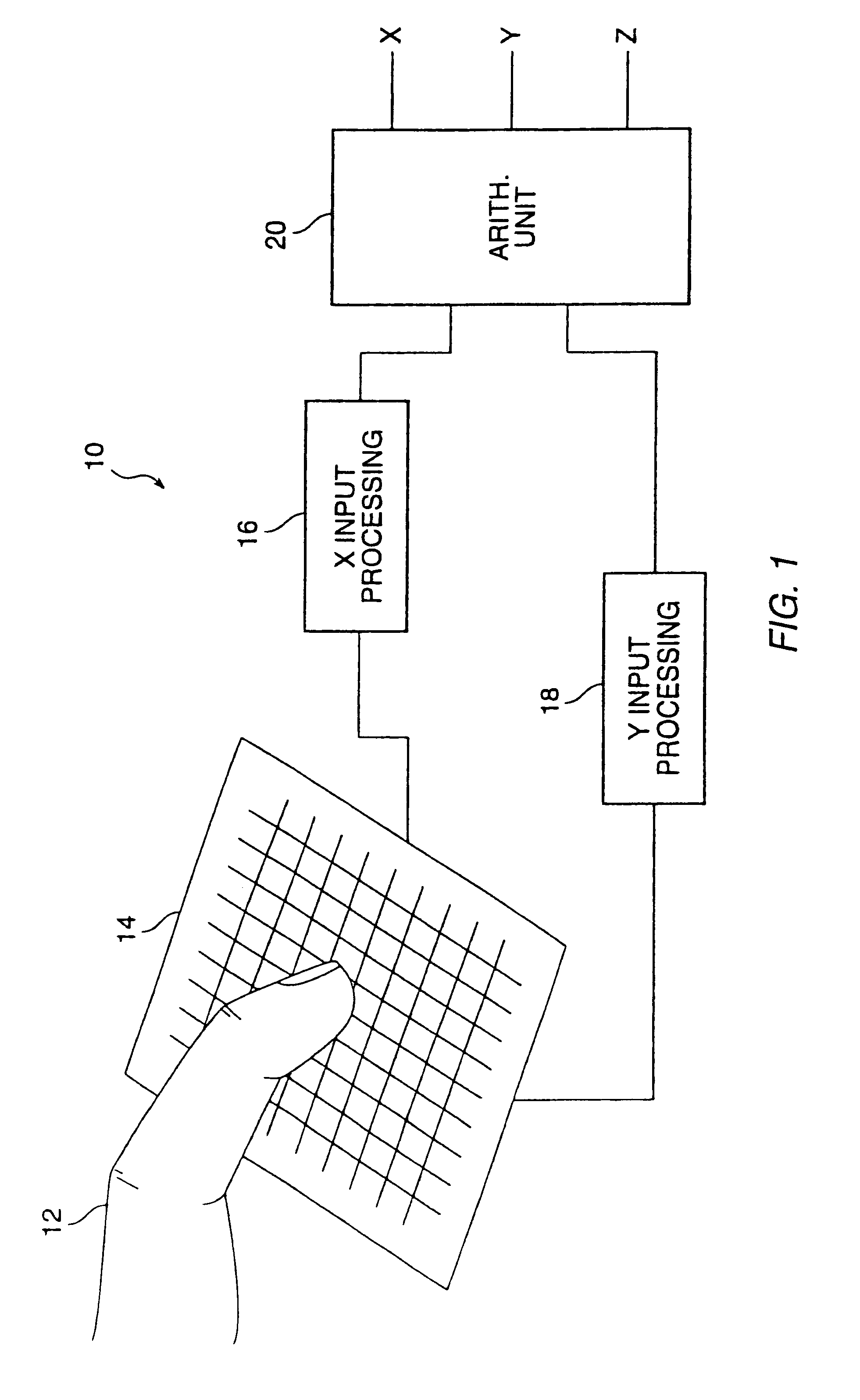
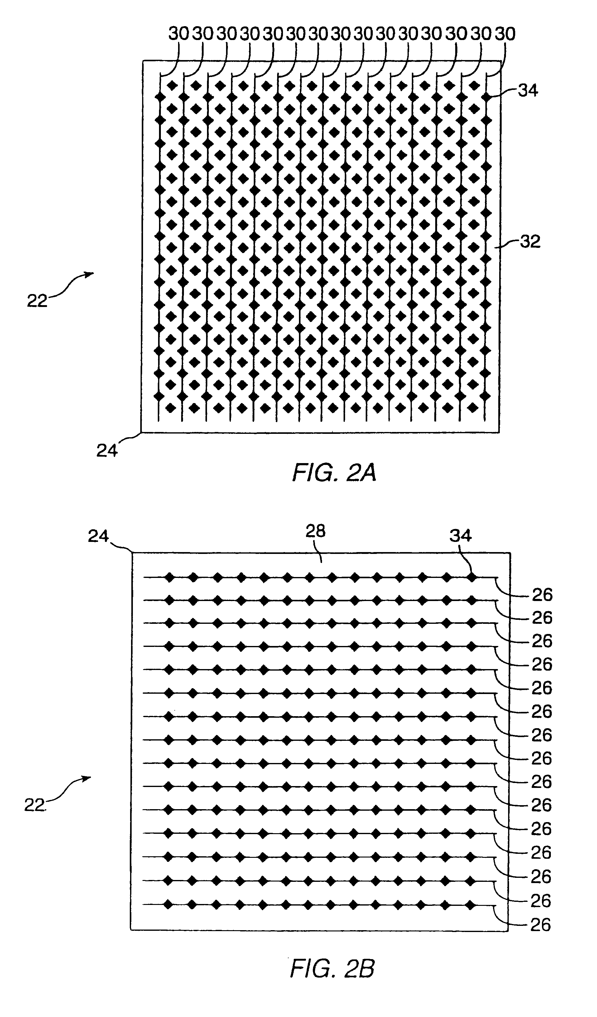
A proximity sensor system includes a sensor matrix array having a characteristic capacitance on horizontal and vertical conductors connected to sensor pads. The capacitance changes as a function of the proximity of an object or objects to the sensor matrix. The change in capacitance of each node in both the X and Y directions of the matrix due to the approach of an object is converted to a set of voltages in the X and Y directions. These voltages are processed by digital circuitry to develop electrical signals representative of the centroid of the profile of the object, i.e, its position in the X and Y dimensions. Noise reduction and background level setting techniques inherently available in the architecture are employed.

Description

1. Field of the InventionThe present invention relates to object position sensing transducers and systems. More particularly, the present invention relates to object position recognition useful in applications such as cursor movement for computing devices and other applications.2. The Prior ArtNumerous devices are available or have been proposed for use as object position detectors for use in computer systems and other applications. The most familiar of such devices is the computer "mouse". While extremely popular as a position indicating device, a mouse has mechanical parts and requires a surface upon which to roll its position ball. Furthermore, a mouse usually needs to be moved over long distances for reasonable resolution. Finally, a mouse requires the user to lift a hand from the keyboard to make the cursor movement, thereby upsetting the prime purpose, which is usually typing on the computer.Trackball devices are similar to mouse devices. A major difference, however is that, u...

Claims


Application Information

Patent Timeline
IPC IPC(8): G06F1/16G06F3/033G06F3/041G06F3/044G06F3/048
CPCG06F1/1626G06F3/044G06F3/041G06F3/03547G06F3/0446G06F3/0445G06F3/04166
Inventor ALLEN, TIMOTHY P.GILLESPIE, DAVIDMILLER, ROBERT J.STEINBACH, GUNTER
Owner SYNAPTICS INC
Learn More