Non-contacting communication and power interface between a printing engine and peripheral systems attached to replaceable printer component

a technology of power interface and printing engine, which is applied in the direction of digital output to print units, instruments, digital computer details, etc., can solve the problems of affecting the reliability of conta

Inactive Publication Date: 2001-05-29
SBC PROPERTIES +1
View PDF5 Cites 31 Cited by
  • Summary
  • Abstract
  • Description
  • Claims
  • Application Information

AI Technical Summary

Benefits of technology

Replaceable printer components, such as toner cartridges, are generally located within and in contact with the printer engine. Contactless power and communications links are established between the replaceable component and the printer engine for peripheral devices installed on or within the replaceable component. Such peripheral devices may include, without limitation a microprocessor, a non-volatile memory, a toner quantity sensor, an environmental condition sensor, a photoconductor condition sensor, or a print quality sensor. For peripheral devices incorporated within or on the replaceable component, power is inductively transferred from a primary winding on the printer engine to an adjacent secondary winding on the replaceable component without the use of direct physical contact between electrical conductors. In addition, communications between the printer engine and at least one peripheral device on board the replaceable component are provided without making direct physical contact between electrical conductors. The communication task is accomplished in one of several ways. For a first embodiment of the invention, control signals are sent from the printer engine to the replaceable component over the inductive power coupling circuit by switching between two frequencies of alternating current applied to the primary winding on the printing engine. The frequency switching is decoded on board the replaceable component to provide contr...

Problems solved by technology

Typically, such contacts are rather delicate, as they must be manufactured with a high degree of mechanical precision in order to maintain a required level of compactness.
Although the sliding action tends to wipe away dirt and other contaminants at the contact site, thus improving the electrical connection, it also creates wear on plated materials.
As the plating is worn away, exposing a base metal more prone to corrosion, c...

Method used


Image

  • Non-contacting communication and power interface between a printing engine and peripheral systems attached to replaceable printer component
  • Non-contacting communication and power interface between a printing engine and peripheral systems attached to replaceable printer component
  • Non-contacting communication and power interface between a printing engine and peripheral systems attached to replaceable printer component

Examples


Embodiment Construction

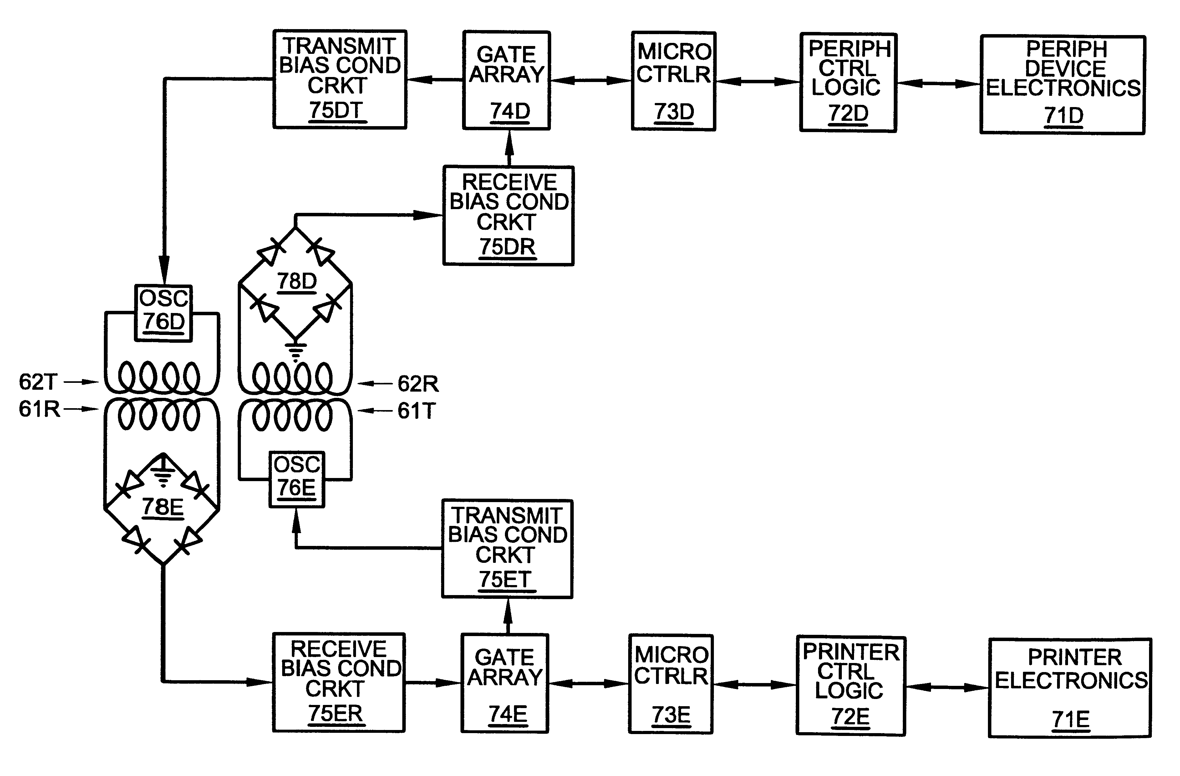
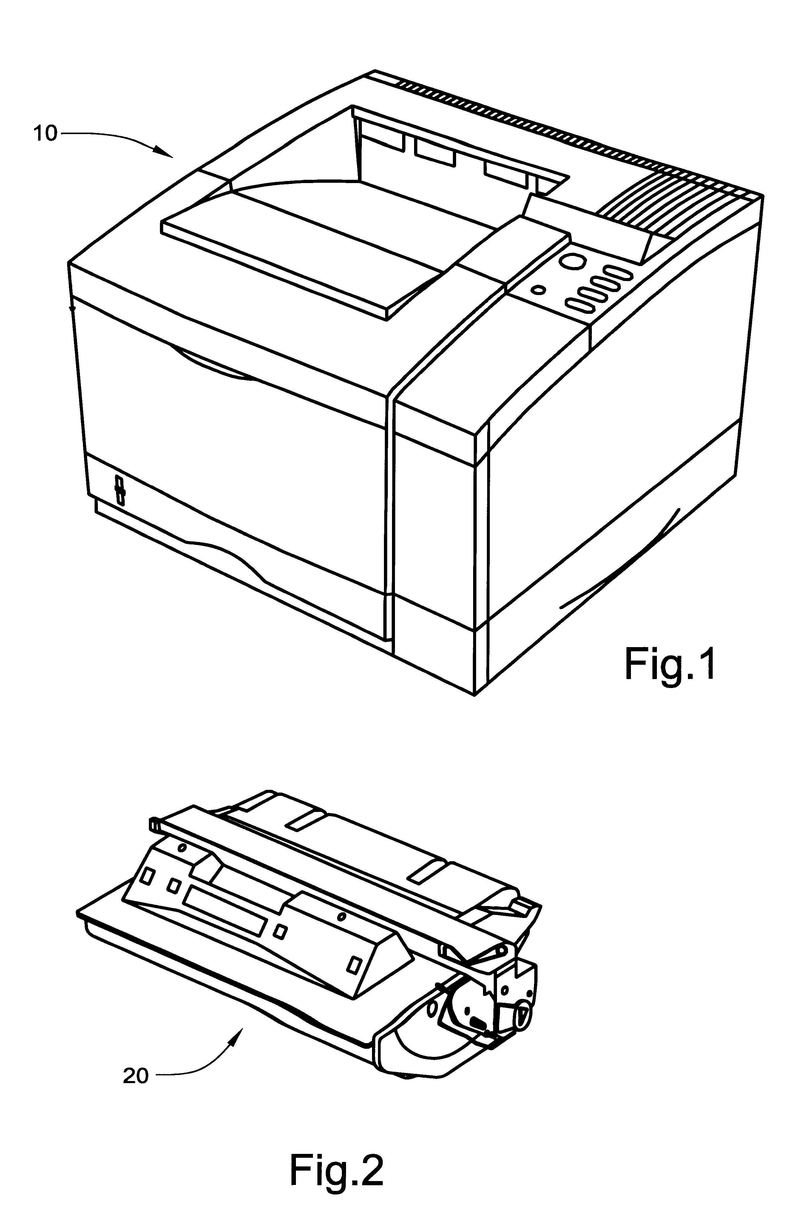
The block diagram of FIG. 1 depicts a laser printer engine 10 of the type having a replaceable printer cartridge. FIG. 2 depicts a replaceable toner cartridge 20 of the type which installs within printer engine 10 such that the toner cartridge 20 is in physical contact with the printer engine. Although the invention is disclosed in the context of a laser printer engine having a removable toner cartridge, the invention is applicable to any removable printer component to which power must be supplied from the printer engine 10 to a peripheral device on a removable component such as a toner cartridge 20. Such peripheral devices may include, without limitation a microprocessor, a non-volatile memory, a toner quantity sensor, an environmental condition sensor, a photoconductor condition sensor, or a print quality sensor. It is intended that the term"printer engine" be broadly interpreted to include any imaging engine utilized in a laser printer, an inkjet printer, a facsimile machine, a p...


PUM


Abstract

Contactless power and communications links are established between a printer engine and a peripheral device installed on a replaceable printer component. For peripheral devices incorporated within or on the replaceable component, power is inductively transferred from a primary winding on the printer engine to an adjacent secondary winding on the replaceable component without the use of direct physical contact between electrical conductors. In addition, communications between the printer engine and at least one peripheral device on board the replaceable component are provided without making direct physical contact between electrical conductors. The communication task is accomplished in one of several ways. For a first embodiment of the invention, control signals are sent from the printer engine to the replaceable component over the inductive power coupling circuit by switching between two frequencies of alternating current applied to the primary winding on the printing engine. The frequency switching is decoded on board the replaceable component to provide control signals for the peripheral device. For communications in the opposite direction, the peripheral device may send information to the printer engine by modulating a resistive load coupled to the secondary winding. Current flow through the primary winding will vary in response to the load on the secondary winding. The variations in current flow on the printer engine side are decoded to signals which the printer engine comprehends. For a second embodiment of the invention, signals are inductively transmitted across a narrow gap. For a third embodiment of the invention, communications are handled by transmitting and receiving modulated infrared energy across a narrow gap.

Description

FIELD OF THE INVENTIONThis invention relates to electronic printers and, more particularly, to printers having attached accessory units which require power and communications connections between the printer and accessory unit.BACKGROUND OF THE INVENTIONThe past twenty years have witnessed an incredible variety of printers designed for digital computers. For years, the line printer was the mainstay of the computer industry. Then, in the mid-1970's, the personal computer revolution began with the appearance of primitive computers based on the S-100 bus. With the appearance of more user-friendly computers from Apple Computer and, later, from IBM Corporation, the demand for personal computers soared. The public's almost insatiable appetite for personal computers has spawned a virtual explosion of technology. Printer technology has been one of the principal beneficiaries of that technology explosion. Early on, dot-matrix printers grabbed the lion's share of the market. For less than a de...

Claims


Application Information

Patent Timeline
IPC IPC(8): B41J29/38B41J29/393G03G15/08G06F3/12B41J29/00H01F38/14
CPCB41J29/393G03G15/0863G03G15/0865G03G15/0855
Inventor HAY, ROBERT R.
Owner SBC PROPERTIES
Why Eureka
Try Eureka