Inexpensive, high quality scanning system

a scanning system and high-quality technology, applied in the field of scanning beam imaging optics, can solve the problems of large imaging errors, difficult to manufacture with high tolerances without increasing costs significantly, and apochromatic telescopes generally imply a high cost, etc., and achieve low design cost, low cost, and high quality.

Inactive Publication Date: 2001-06-05
RIBES ALFONSO CARLOS +2
View PDF10 Cites 19 Cited by
  • Summary
  • Abstract
  • Description
  • Claims
  • Application Information

AI Technical Summary

Benefits of technology

The present invention provides an inexpensive, simple, compact optical relay for use primarily with scanning beam imaging systems. The optical relay, which is also known as an optical telescope or optical coupler, consists of two telescope or microscope eyepieces forming an afocal assembly. A beam pivoting about a stationary point in the first focal plane of the first eyepiece will be relayed through the optical system such that it pivots about a stationary point on the second focal plane of the second eyepiece. In the preferred embodiment a collimated beam is pivoted about the first focal point (on the optic axis) of an eyepiece. The beam passes through the first and second eyepieces which form a 1:1 relay, or a unitary telescope, in the preferred embodiment. The emerging beam pivots about the second focal point of the second eyepiece. The entrance and emerging beams have the same diameters and pivot angles (opposite sign). This optical relay can be used with a wide variety of entrance beam diameters and angles while still providing a high quality exit beam. The key to the success of the present invention is due to economics rather than optics. Telescopes and microscopes are found in large numbers throughout the world and, therefore, so are their corresponding eyepieces. Designs for most commonly used eyepieces have been established for many decades. Eyepiece manufacturers therefore enjoy low design costs and utilize mass production and economies of scale to produce high quality, low cost eyepieces. The use of commercial eyepieces in the present invention provides for a high quality, inexpensive optical telescope. The wide variety and availability of eyepieces allows for a flexible relay optic design with a wide degree magnification, entrance / exit beam diameter, and entrance / exit beam angle possibilities.

Problems solved by technology

This is especially true in confocal microscopy where even small aberrations can result in large imaging errors.
High quality plan apochromatic telescopes generally imply a high cost.
Telescopes constructed with off-axis parabolic mirrors (Amos, U.S. Pat. No. 4,997,242) provide operation for beam diameters and scan angles larger than achromats but are difficult to manufacture with high tolerances without increasing costs significantly.
Mirrors tend to degrade with time and are generally less light efficient than refractive optics.

Method used


Image

  • Inexpensive, high quality scanning system
  • Inexpensive, high quality scanning system
  • Inexpensive, high quality scanning system

Examples


Embodiment Construction

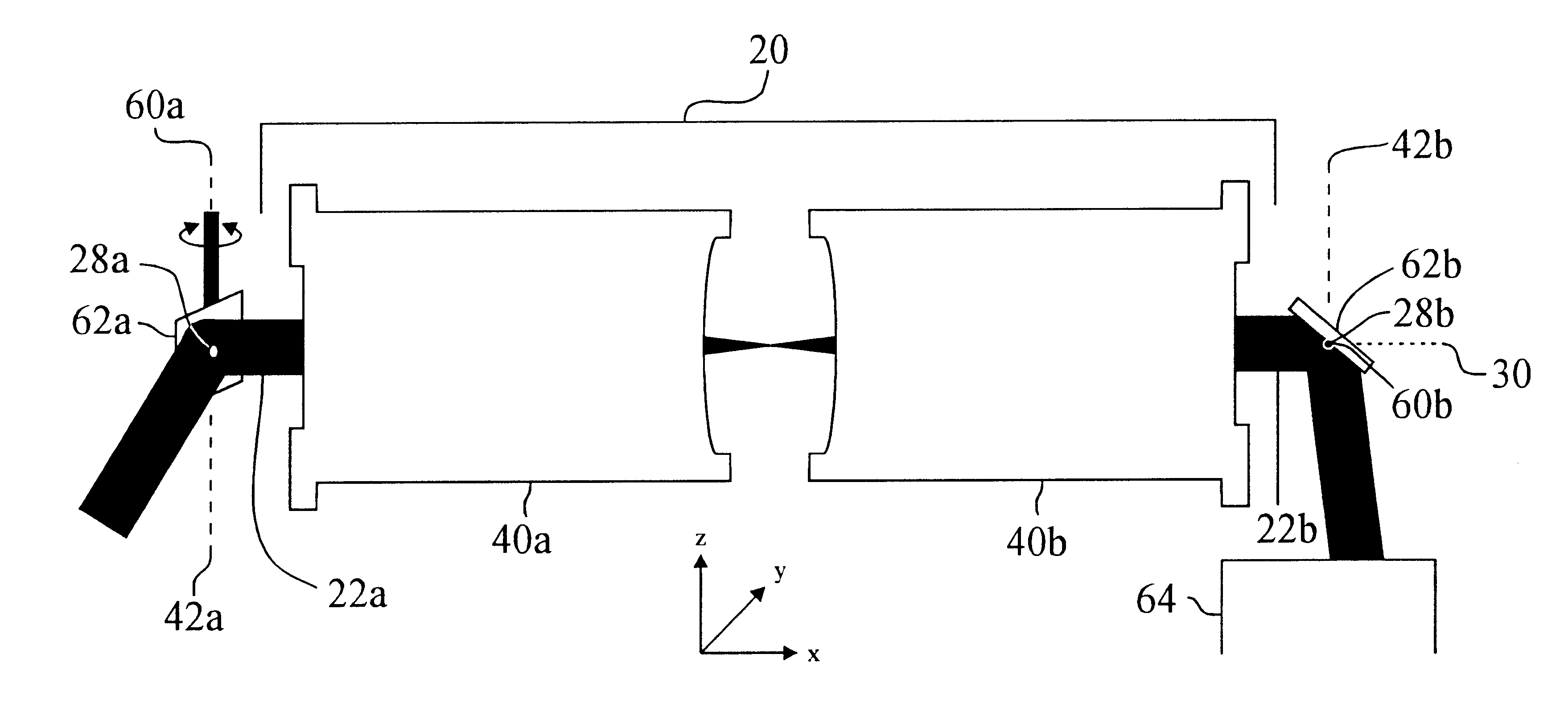
The present invention consists of a pair of eyepieces arranged in an afocal assembly. This assembly acts as a high quality, inexpensive, and compact optical relay for use primarily in scanning beam imaging instrumentation. The optical quality is such that it can also be used in confocal scanning beam imaging systems.

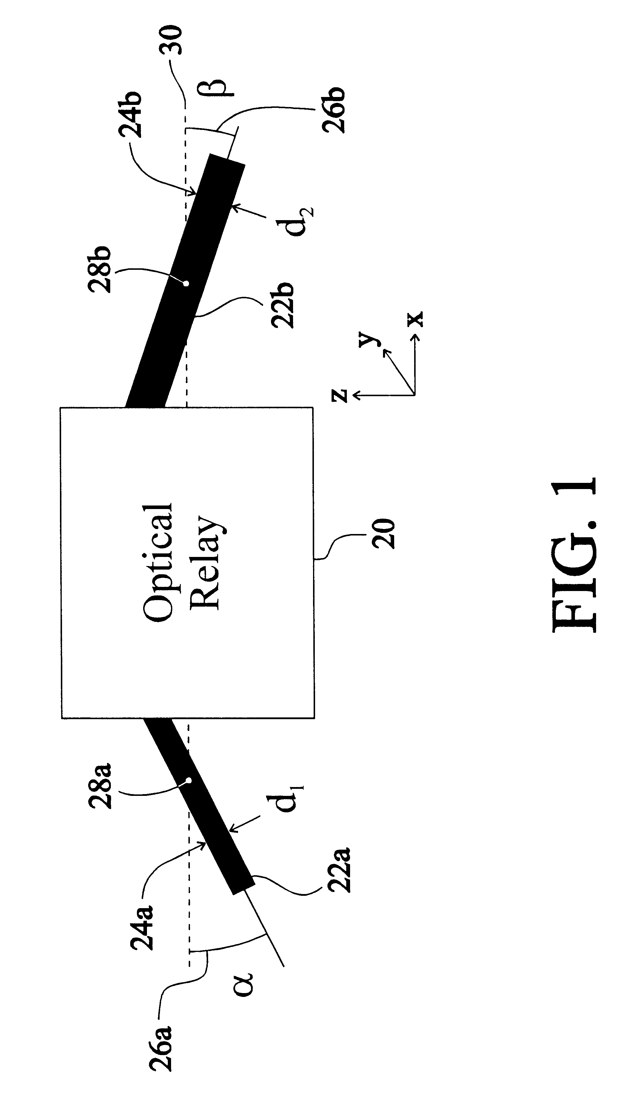
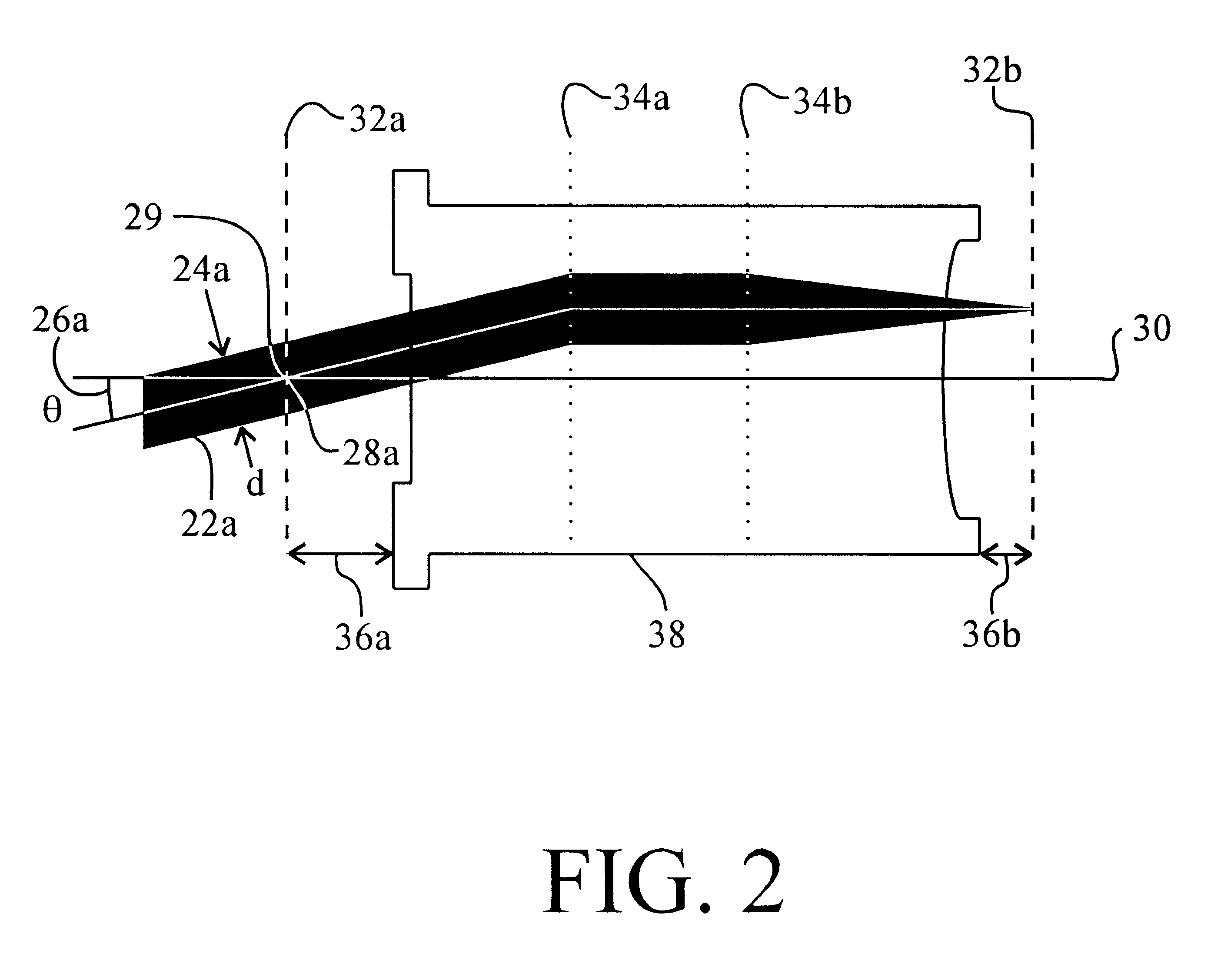
FIG. 1 shows a generic or generalized optical relay 20. The optical relay can consist of any combination of lenses, mirrors, diffractive optics, etc. A collimated beam of light 22a with beam diameter 24a equal to d.sub.1 enters the optical relay. The collimated entrance beam 22a enters the optical relay at an angle 26a equal to .alpha. with respect to the optic axis 30. The entrance beam pivots about the entrance pivot point 28a. The purpose of the optical relay is to accept a collimated beam pivoting about a fixed point and relay this motion such that a collimated exit beam 22b (not necessarily the same beam diameter or scan angle) with diameter d.sub.2 24b and scan ang...


PUM


Abstract

The present invention provides an inexpensive, simple, compact, optical relay for use primarily with scanning beam imaging systems. More specifically, it can be used as an optical interconnect between scanning mirrors and between a scanning mirror and imaging optics such as a microscope objective. The optical relay, also known as an optical telescope or coupler, consists of two eyepieces forming an afocal assembly. A beam pivoting about a stationary point in the first focal plane of the first eyepiece will be relayed through the optical system such that it pivots about a stationary point at the second focal plane of the second eyepiece. In the preferred embodiment a collimated beam pivots about the first focal point of the first eyepiece as it enters the optical relay, and exits the optical relay with the same beam diameter and scan angle (opposite sign) pivoting about the second focal point of the second eyepiece.

Description

BACKGROUND--FIELD OF INVENTIONThe invention relates to scanning beam imaging optics with particular emphasis on confocal microscopy and macroscopy.BACKGROUND--DISCUSSION OF PRIOR ARTOptical telescopes used as relay optics or optical couplers must be well-corrected to function properly. This is especially true in confocal microscopy where even small aberrations can result in large imaging errors. High quality plan apochromatic telescopes generally imply a high cost. In practice, high quality telescopes are not used in scanning beam imaging as individual components, rather they form part of pre-existing conventional wide-field microscopes. Telescopes made with singlets, achromatic doublets, or spherical mirrors are inexpensive but only work with very small beam diameters and scan angles. Telescopes constructed with off-axis parabolic mirrors (Amos, U.S. Pat. No. 4,997,242) provide operation for beam diameters and scan angles larger than achromats but are difficult to manufacture with ...

Claims


Application Information

Patent Timeline
Patent Type & Authority Patents(United States)
IPC IPC(8): G02B26/10G02B23/00G02B21/00G02B13/00
CPCG02B13/0095G02B21/0036G02B21/0072G02B23/00G02B26/105
Inventor RIBES, ALFONSO CARLOSDIXON, ARTHUR EDWARDDAMASKINOS, SAVVAS
Owner RIBES ALFONSO CARLOS
Why Eureka
Try Eureka