Fibers with optical function

Inactive Publication Date: 2001-06-05
NISSAN MOTOR CO LTD +2
View PDF25 Cites 33 Cited by
  • Summary
  • Abstract
  • Description
  • Claims
  • Application Information

AI Technical Summary

Benefits of technology

Dicarboxilic acid with alkyl group, particularly, methyl group, in the side chain includes, preferably, dicarboxilic acid having the side chain out of aliphatic carbon such as 4,4'-diphenyl isopropylidene dicarboxilic acid, 3-methyl glutaric acid, or methyl malonic acid in view of easy orientation of alkyl group outward of a molecule, and thus easy interaction with polymethyl methacrylate. Moreover, glycol with alkyl group, particularly, methyl group, in the side chain includes, more preferably, to glycol having the side chain out of aliphatic carbon such as neopentyl glycol, bisphenol A, or bisphenol A with ethylene oxide added in view of easy interaction with polymethyl methacry

Problems solved by technology

However, an improvement in deep color of fibers causes a reduction in luster thereof due to occurrence of dullnes and degradation of brightness.
The two are very difficultly compatible with each other.
The fibers produce slight coloring by reflection and interference of light, but cannot show a deep interference color having a reflection spectrum with a predetermined wavelength due to insufficient number of layers.
However, lamination of such flat filaments enables difficultly the thickness which allows interference of light, merely serving, theoretically, to restrain reflection light.
The references fail to sho

Method used


Image

  • Fibers with optical function
  • Fibers with optical function
  • Fibers with optical function

Examples


examples 6-9

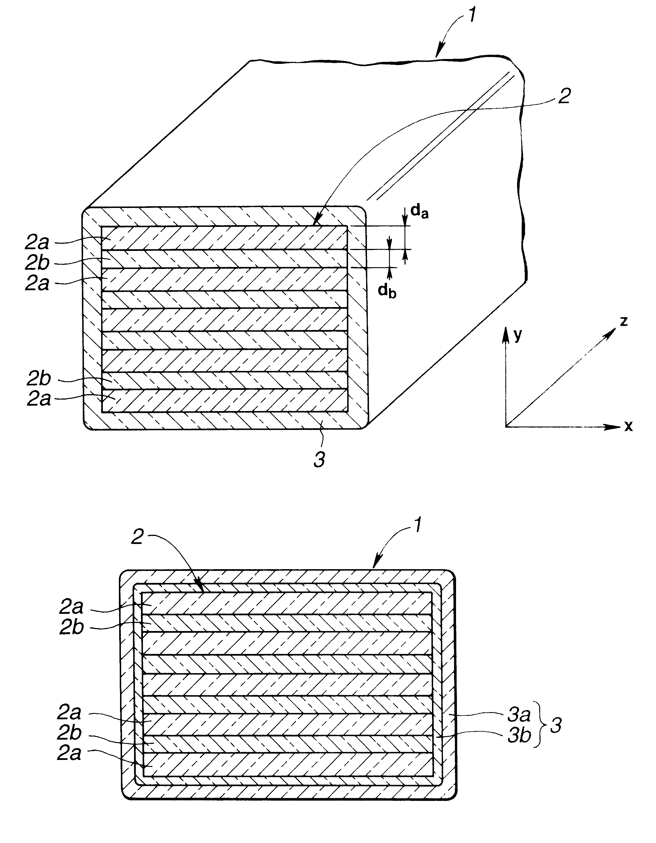
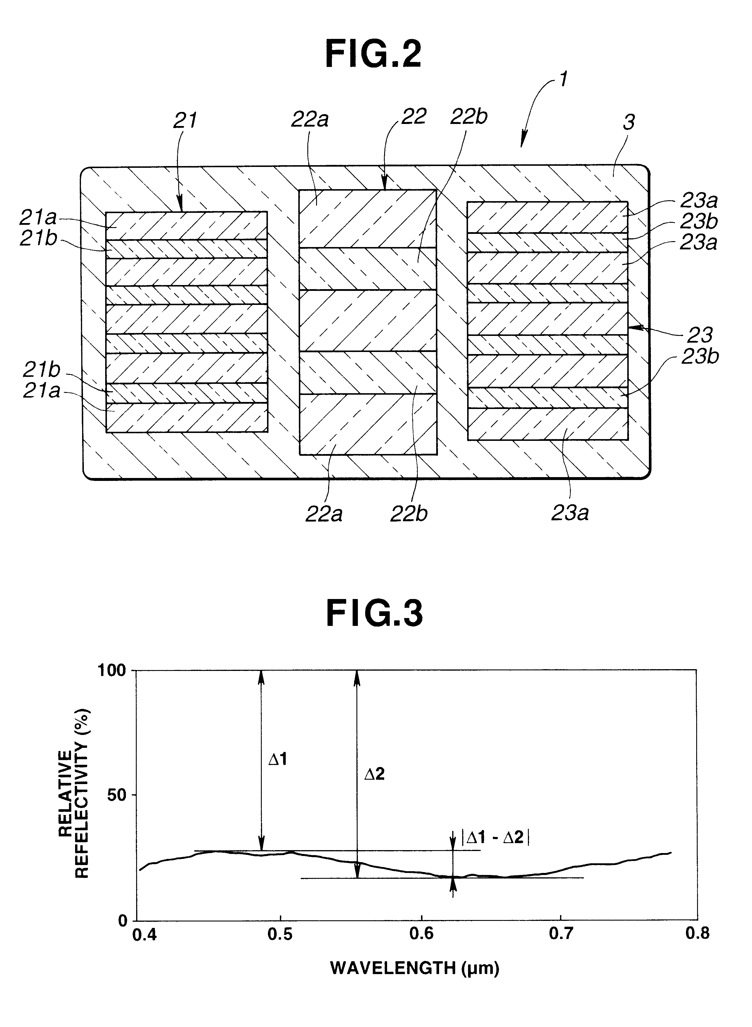
and comprative examples 2-3 will be described. In the examples 6-9, using Panlight AD-5503 manufactured by TEIJIN LTD. as PC as the polymer A with greater refractive index and Acripet MF (melt flow rate at 230.degree. C.=14) manufactured by Mitsubishi Rayon Co., Ltd. as PMMA as the polymer B with smaller refractive index, composite spinning is carried out at a take-up speed of 1,500 m / min. to obtain the fibers including the core 43 and the clad 44 arranged therearound as shown in FIG. 10A. The number of laminations of PC and PMMA layers 41, 42 is 20. In the comparative examples 2-3, fibers including the core 43 only and no clad 44 are manufactured in the same way. Those fibers are stretched by a roller stretching machine by 1.8 times to obtain stretched threads with 12 filaments. The section of each stretched thread is photographed by an electron microscope to measure the thicknesses of the PEC layer 41, the PMMA layer 42, and the clad 44 in the center of the section and a point the...

examples 10-11

and a comparative example 4 will be described. Using PET as the polymer A with greater refractive index and PMMA as the polymer B with smaller refractive index, composite spinning is carried out in substantially the same way as in the examples 1 and 6 to obtain the fiber as shown in FIG. 10A (example 10), the fiber as shown in FIG. 14A including the reinforcement 45 arranged in the core 43 and having substantially the same thickness as that of the clad 45 (example 11), and a fiber including the core 43 only and no clad 44 (comparative example 4). The tensile strength of the fibers is measured, the results of which are given in FIG. 15. FIG. 15 reveals that formation of the clad 44 contributes to a large improvement and further increase in tensile strength.

examples 12-16

will be described. Using PET as the polymer A with greater refractive index and PMMA as the polymer B with smaller refractive index, composite spinning is carried out in substantially the same way as in the examples 1 and 6 to obtain the fiber as shown in FIG. 10A. With the same structure of the core 43, the thickness of the clad 44 of PET is determined differently in the exmaples: 1.0 .mu.m in the example 12, 2.0 .mu.m in the example 13, 4.0 .mu.m in the example 14, and 6.0 .mu.m in the example 15. The tensile strength of the fibers is measured, the results of which are given in FIG. 16. FIG. 16 reveals that the fiber with the clad 44 in the examples is greater in tensile strength than the fiber with no clad 44 in the comparative example 4 (see a in FIG. 15), that with the thickness of the clad 44 more than 1.0 .mu.m, the tensile strength is greater than 1.0 g / d to show a practical value, and that as the thickness of the clad 44 increases, the tensile strength of the fiber also inc...


PUM

PropertyMeasurementUnit
Fractionaaaaaaaaaa
Lengthaaaaaaaaaa
Thicknessaaaaaaaaaa

Abstract

A fiber with a cross section having x-axis and y-axis directions includes an alternate lamination including a predetermined number of a first portion and a second portion adjacent thereto, which have different optical characteristics, and a clad arranged around the alternate lamination.

Description

The present invention relates to fibers with optical function which ensure reflection and interference of radiation with a predetermined wavelength in the visible, infrared, or ultraviolet region.Recently, many attempts are carried out to obtain a higher fabric quality by improving feeling of cloths through modification of the fiber section from a circle to, e.g. a star or combination of two or more polymers.However, an improvement in deep color of fibers causes a reduction in luster thereof due to occurrence of dullnes and degradation of brightness. On the other hand, an improvement in luster causes a reduction in deep color due to increased surface reflection. The two are very difficultly compatible with each other.JP 43-14185 discloses iridescent coated-type composite fibers including three layers. The fibers produce slight coloring by reflection and interference of light, but cannot show a deep interference color having a reflection spectrum with a predetermined wavelength due t...

Claims


Application Information

Patent Timeline
IPC IPC(8): D01F8/04D01F8/14D01D5/00D01D5/30D01D5/32D01D5/253
CPCD01D5/253D01D5/30D01D5/32D01F8/04D01F8/14
Inventor OWAKI, SHINJIKURODA, TOSHIMASASHIMIZU, SUSUMUSAKIHARA, AKIOKUMAZAWA, KINYATABATA, HIROSHIASANO, MAKOTOTAKAHASHI, HIDEKAZU
Owner NISSAN MOTOR CO LTD
Why Eureka
Try Eureka