
Apparatus for the recovery of dragged-out treatment solutions by immersion barrels

Inactive Publication Date: 2001-06-12
HENIG HANS
View PDF10 Cites 3 Cited by
  • Summary
  • Abstract
  • Description
  • Claims
  • Application Information

AI Technical Summary

Benefits of technology

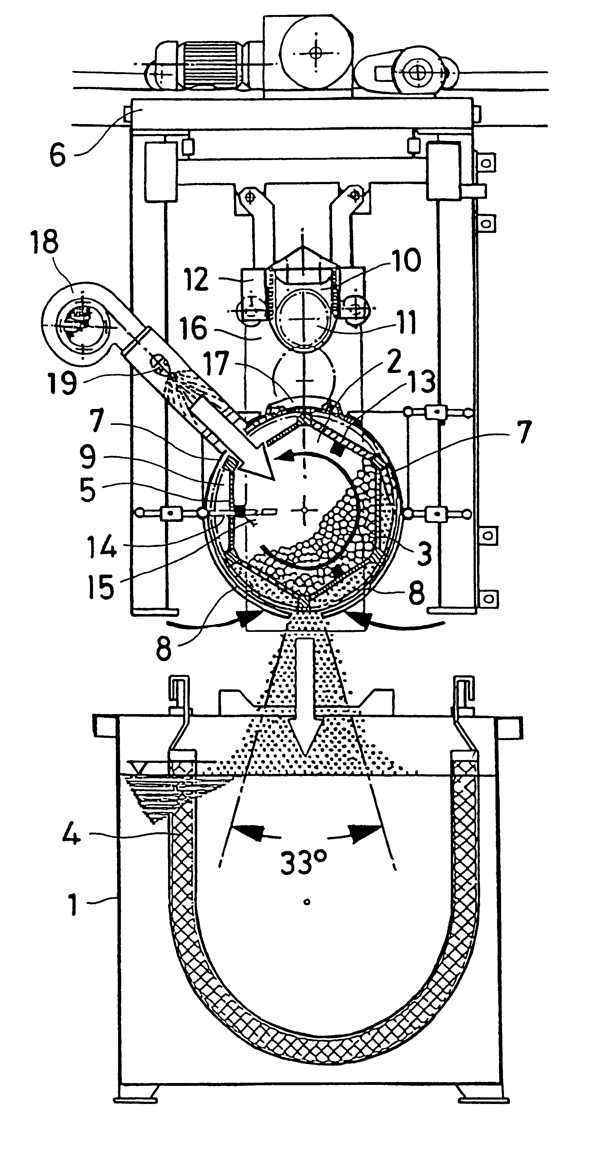
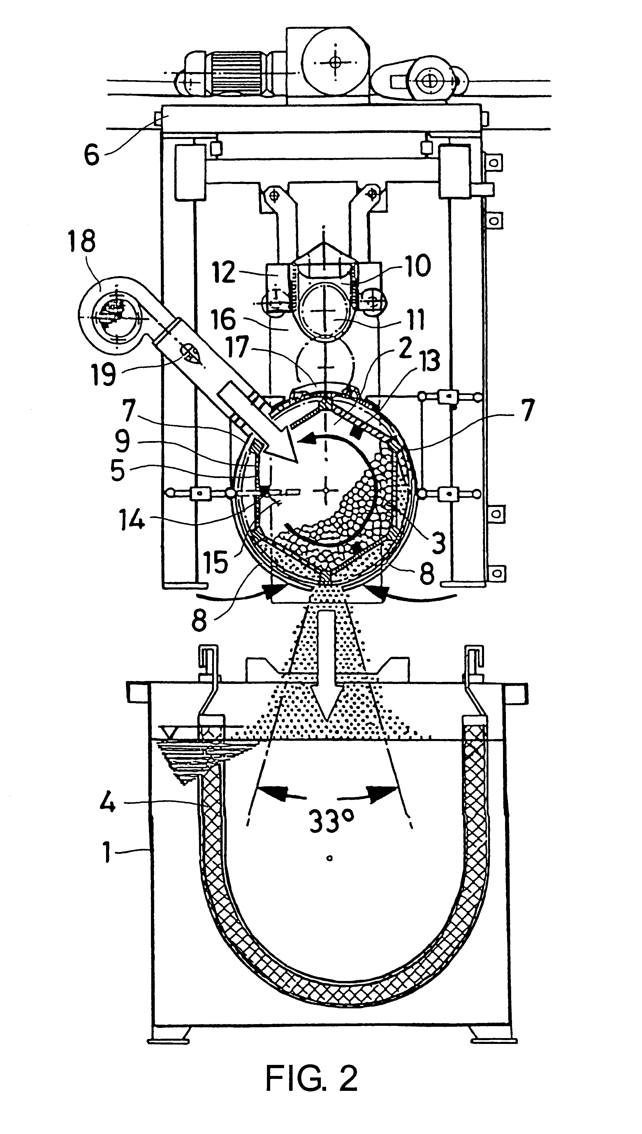
The drastically reduced air volume of the narrow jet prevents the current of air from spreading beyond the edges of the tank and additional constructional measures for controlling the movement of air caused by the flow of air out of the compressed-air chamber--one of the principal disadvantages according to the prior art--are no longer necessary.
The central position of the outlet nozzle at the base of the chamber further ensures that the flow of the relatively small volume of air aligned directly towards the middle of the tank remains to a large extent free from secondary interfering turbulences with the moved ambient air.

Problems solved by technology

The quantity of water delivered without pressure has an extremely low process efficiency.
The described known apparatus furthermore requires a large amount of apparatus.
The mechanism required for carrying and for simultaneously and synchronously moving the two half-shells on the carriage is costly to produce, complex and difficult to service.
The aforementioned design solution obviously results in a substantially greater structural height which is disadvantageous for the erection of the barrel installation.
The complicated mechanism, which is not easily accessible, is awkward to service; it is also exposed without protection to the corrosive air within the operating room.
Although German Patent Specification DE 38 30 237 C2 proposes a simplified solution to the problem, which obviously reduces the production costs and facilitates servicing, it has disadvantages of a process nature.
Particular difficulties occur in the case of bath solutions with high operating temperatures.
In summary, it may be stated that, in many cases, the known apparatus and associated methods according to the prior art are not capable, or are capable only to a limited extent, of fulfilling the stringent requirements of operating practice.

Method used


Image

  • Apparatus for the recovery of dragged-out treatment solutions by immersion barrels
  • Apparatus for the recovery of dragged-out treatment solutions by immersion barrels
  • Apparatus for the recovery of dragged-out treatment solutions by immersion barrels

Examples


Embodiment Construction

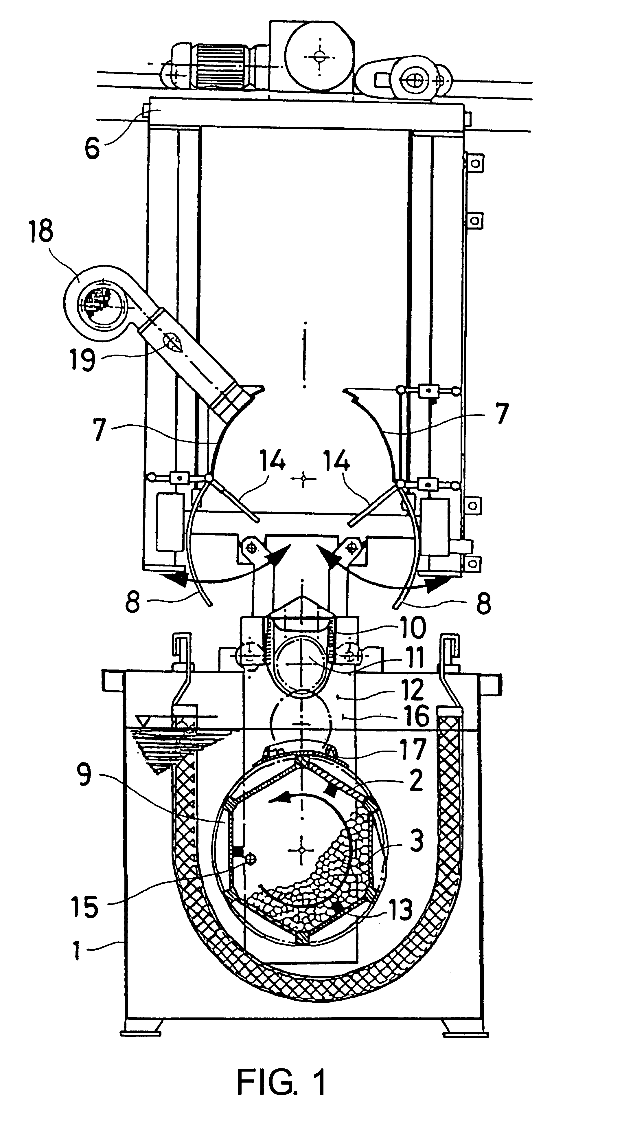
Apparatus according to the invention has the compressed-air chamber connected to a compressed-air line (usually from a centrifugal fan) and, simultaneously, to a water supply line. The methods according to the invention for the application of the aforementioned apparatus which have as their object the recovery of the dragged-out bath solutions are composed of sequences of combined steps of which the fundamental elements consist of the current of air introduced into the compressed-air chamber and of defined quantities of injected water.

The downwardly directed current of air flows transversely through the compressed-air chamber, and so also transversely through the immersion barrel positioned within it and through the charge contained within the barrel. This performs the function, as a motive driving force and a means of transportation, of intercepting, entraining and drawing off and returning downwards directly into tank located therebelow, the treatment solution in concentrated form...


PUM

PropertyMeasurementUnit
Pressureaaaaaaaaaa
Pressureaaaaaaaaaa
Angleaaaaaaaaaa

Abstract

Apparatus and a method for the direct recovery of residual quantities of an aqueous solution adhering to pourable mass parts following an electrolytic and / or chemical surface treatment on the parts, in the course of which the parts are carried in a perforated immersion barrel supported on a movable carriage of a barrel treatment installation. A compressed-air chamber is provided on the carriage, into which the barrel is moved, the chamber being provided with a compressed air source to cause a current of air to flow transversely through the chamber. The compressed-air chamber essentially comprises a horizontal, upwardly cylindrically convex upper half-shell which is fixed on the carriage and which encompasses in a substantially air-tight manner the upper half of the immersion barrel when the barrel has been positioned within the chamber, and a pair of horizontal, lateral, lower, outwardly cylindrically convex quarter-shells which are capable of movement towards and away from one another. When moved together, the quarter-shells encompass the lower half of the immersion barrel in a substantially air-tight manner, except that the two quarter-shells leave open a relatively narrow longitudinal slot between their two lowermost long edges. The current of air passes into the chamber and after passing through the barrel and over its contents, leaves the chamber downwardly, entraining any dragged-out solution in the air stream. Water may be injected into the air stream, to assist removal from the parts of the dragged-out solution.

Description

BACKGROUND TO THE INVENTION1) Field of the InventionThe invention concerns a method and associated apparatus for the direct recovery, following an electrolytic and / or chemical surface treatment, of residual quantities of an aqueous solution adhering to a charge of pourable mass parts in a movable perforated immersion barrel. The immersion barrel is moved to be positioned in a compressed-air chamber, connected to a centrifugal fan, on a carriage of a barrel installation. A current of air flowing transversely through said chamber entrains the solution residue adhering to the charge into a tank located below the chamber.2) Description of the Prior ArtSuch an apparatus for performing the described above method is known from German Patent Specification DE 31 33 629 C2. The immersion barrel which is attached to the carriage is moved out of the treatment solution tank into a compressed-air chamber and when positioned therein, is subjected together with the contained charge of pourable mass...

Claims


Application Information

Patent Timeline
IPC IPC(8): C23G3/00C25D21/18C25D21/00F26B11/18F26B11/00
CPCC23G3/00C25D21/18F26B11/181
Inventor HENIG, HANS
Owner HENIG HANS
Learn More