
Digital ultrasonic monitoring system and method

a digital ultrasonic and monitoring system technology, applied in the field of digital ultrasonic monitoring devices, can solve the problems of creating ultrasonic noise, ultrasonic sound waves with a frequency too high for human ear detection, and soapy water bubbles

Inactive Publication Date: 2001-06-19
COMPUTATIONAL SYST
View PDF26 Cites 87 Cited by
  • Summary
  • Abstract
  • Description
  • Claims
  • Application Information

AI Technical Summary

Benefits of technology

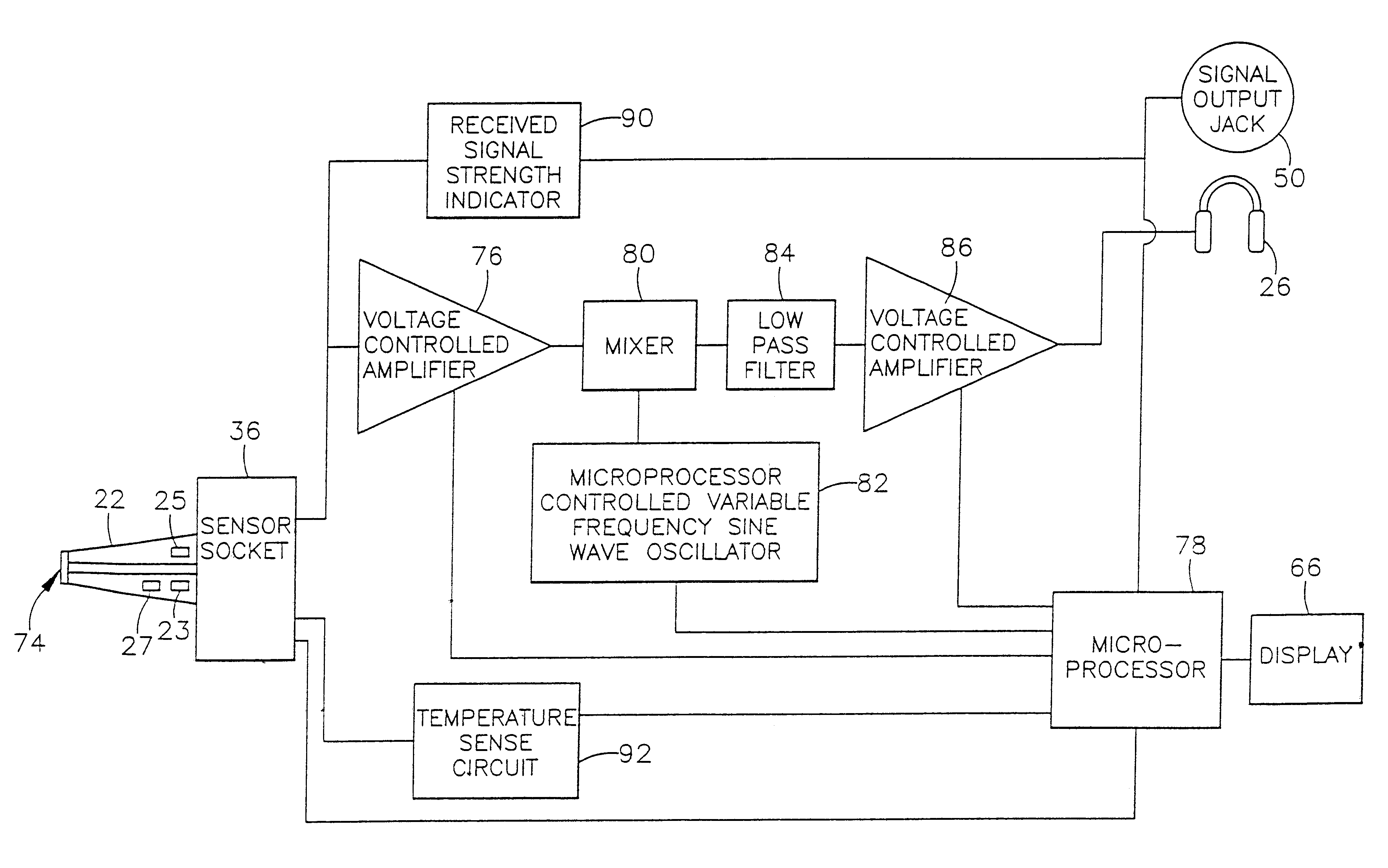
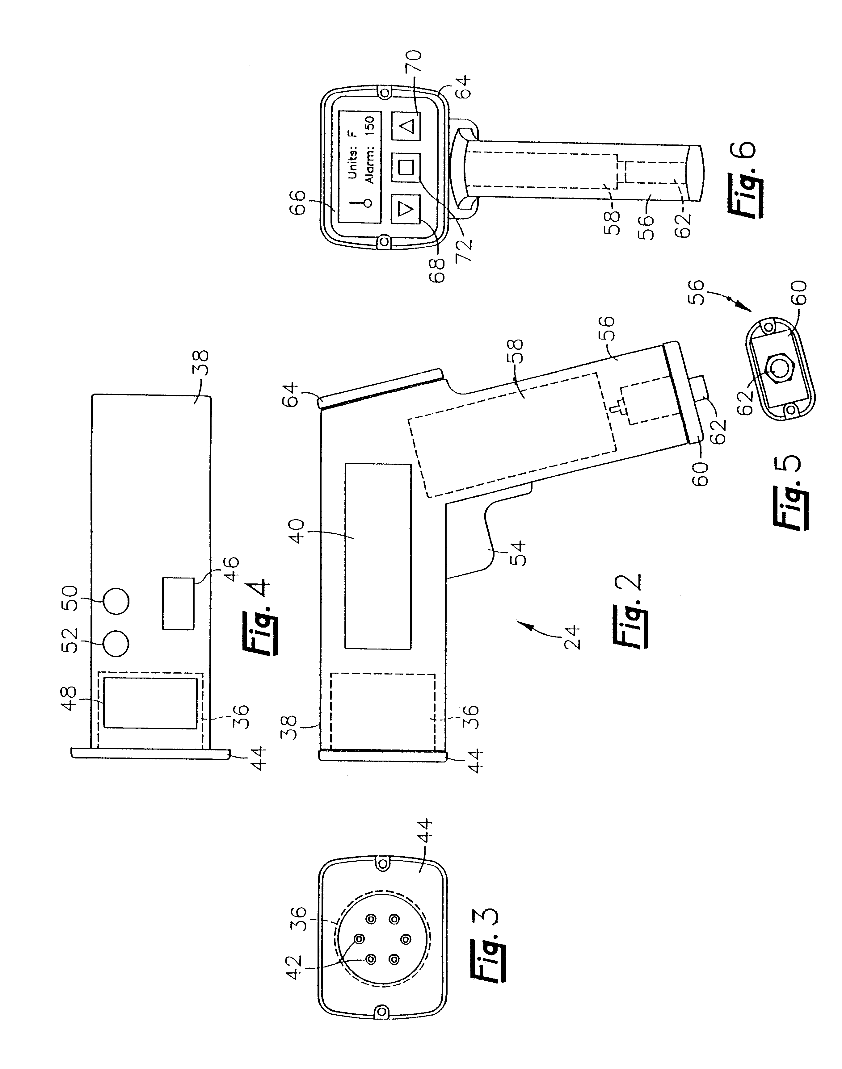
In an especially preferred embodiment, user control of the digital ultrasonic monitoring device is provided by a series of inputs and a display. A mode key user input located on the elongate housing allows the user to select an operating mode for the digital ultrasonic device. An up arrow key and a down arrow key user input allow the user to enter commands that control functions such as the frequency range in which the digital ultrasonic device will operate and the gain of the first and second voltage controlled amplifiers. A display, preferably an LCD, displays a received signal strength bar graph, a received signal strength level, a temperature reading, a battery level indicator, and a monitoring frequency value in an easily readable format.
A communications port located underneath the barrel shaped portion of the elongate housing allows the microprocessor and memory in the digital ultrasonic device to communicate with a host computer. A signal output provides a signal that is the detected envelope waveform of the ultrasonic signal. This signal consists of instantaneous points on the waveform that have a DC value directly related to the signal strength in decibels of the ultrasonic electrical signal at that point. This signal output can be provided to a machine analyzer so that frequency and time domain analysis can be performed on the ultrasonic envelope waveform. Preferably, an infrared communications port is provided that allows the digital ultrasonic device to wirelessly communicate with an external infrared communications port located on another device.

Problems solved by technology

Most industrial processes, including almost all sources of friction, create some ultrasonic noise.
For example, leaks in pipes, machinery defects and electrical arcing produce ultrasonic sound waves that have a frequency that is too high for the human ear to detect.
If a leak was present, bubbles would form in the soapy water where the gas was escaping.
These analog ultrasonic instruments suffer from many drawbacks.
For example, the analog instruments do not provide a quantitatively referenced power level of the signal to the user.
This is undesirable because it makes it difficult to compare readings taken at one point in time to readings taken at a later point in time.
Also, prior art analog instruments did not employ analog to digital converters or microprocessors, making it difficult for them to perform advanced signal analysis techniques on the ultrasonic electrical signals.

Method used


Image

  • Digital ultrasonic monitoring system and method
  • Digital ultrasonic monitoring system and method
  • Digital ultrasonic monitoring system and method

Examples


Embodiment Construction

)

The ultrasonic monitoring system of the present invention effectively locates leaks of air, steam, or other gases from pressurized systems as well as arching and electrical corona, which may produce ultrasonic sounds. Furthermore, the ultrasonic monitoring system can also diagnose and analyze steam trap operation, bearing and gear defects, cavitation and surging in pumps and compressors, lubrication problems in dynamic equipment, valve operation, steam lines, and piston friction and detonation problems in reciprocating equipment.

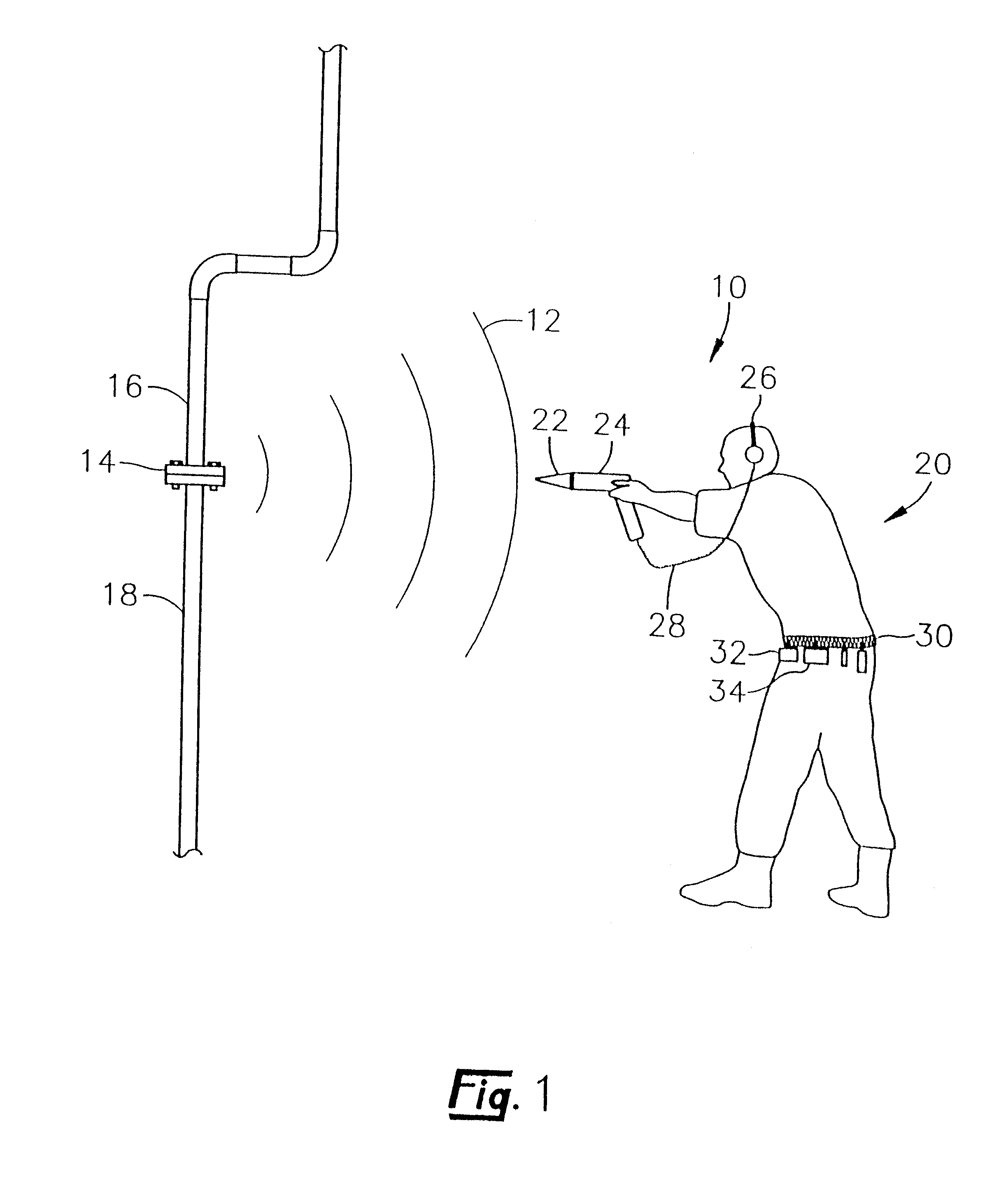
Referring now to FIG. 1, an especially preferred ultrasonic monitoring system 10 for detecting and monitoring ultrasonic sound waves 12 is shown. The ultrasonic sound waves 12 are emanating from the intersection 14 of two abutting pipes 16 and 18. In the case of leak detection, the ultrasonic monitoring system 10 is principally used by the operator 20 to determine the location from which the ultrasonic sound waves 12 are emanating. The ultrasonic monitoring...


PUM


Abstract

A portable digital ultrasonic monitoring system and method for use by an operator in detecting the ultrasonic waves and temperature variations produced by sources such as leaks in pipes, arcing, electrical corona and machinery defects is provided. The digital ultrasonic monitoring system includes a microprocessor based system in a hand held elongate housing that digitally analyzes and stores information received from its sensors. The digital ultrasonic monitoring system provides a referenced decibel output reading of the signal strength of the received ultrasonic signals. In addition, a heterodyned type audio signal that is related to the sensed ultrasonic signals is provided to the operator through a pair of headphones. The portable device has user input keys that allow the operator to select from a variety of different operating modes. A display displays a variety of different readings depending upon the operating mode of the device.

Description

1. Field of the InventionIn general, the present invention relates to a digital device for detecting and monitoring ultrasonic waves. In particular, the present invention relates to a portable ultrasonic monitoring instrument that utilizes a microprocessor to analyze and store information about detected ultrasonic waves in order to locate leaks and machinery defects.2. Background of the InventionThe normal frequency range for human hearing is roughly 20 to 20,000 hertz. Ultrasonic sound waves are sound waves that are above the range of human hearing and, thus, have a frequency above about 20,000 hertz. Any frequency above 20,000 hertz may be considered ultrasonic. Most industrial processes, including almost all sources of friction, create some ultrasonic noise. For example, leaks in pipes, machinery defects and electrical arcing produce ultrasonic sound waves that have a frequency that is too high for the human ear to detect. In the past, analog ultrasonic sensors have been used in ...

Claims


Application Information

Patent Timeline
IPC IPC(8): G01N29/44G01N29/36G01M3/24G01N29/14G01H3/00G01H1/00
CPCG01H1/003G01H3/00G01M3/24G01M3/243G01N29/14G01N29/36G01N29/44G01N29/4454
Inventor BATTENBERG, REXFORD A.CARPENTER, TERRY G.JOHNSON, WILLIAM S.PIETY, KENNETH R.PUTERBAUGH, KENNETH C.ROBINSON, JAMES C.VANVOORHIS, JAMES B.
Owner COMPUTATIONAL SYST
Learn More