

Power tool control system
- Summary
- Abstract
- Description
- Claims
- Application Information
AI Technical Summary
Benefits of technology
Problems solved by technology
Method used
Image

Examples
Embodiment Construction
[0171] Reference will now be made in detail to the presently preferred embodiments of the invention, examples of which are illustrated in the accompanying drawings.
[0172] Referring generally now to FIGS. 1 through 142, exemplary embodiments of the present invention are shown.
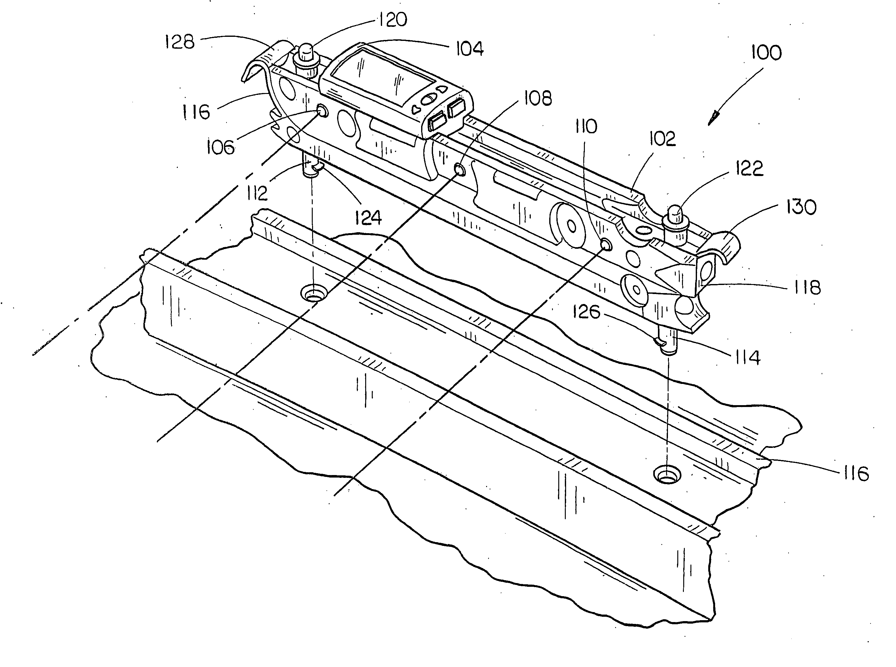
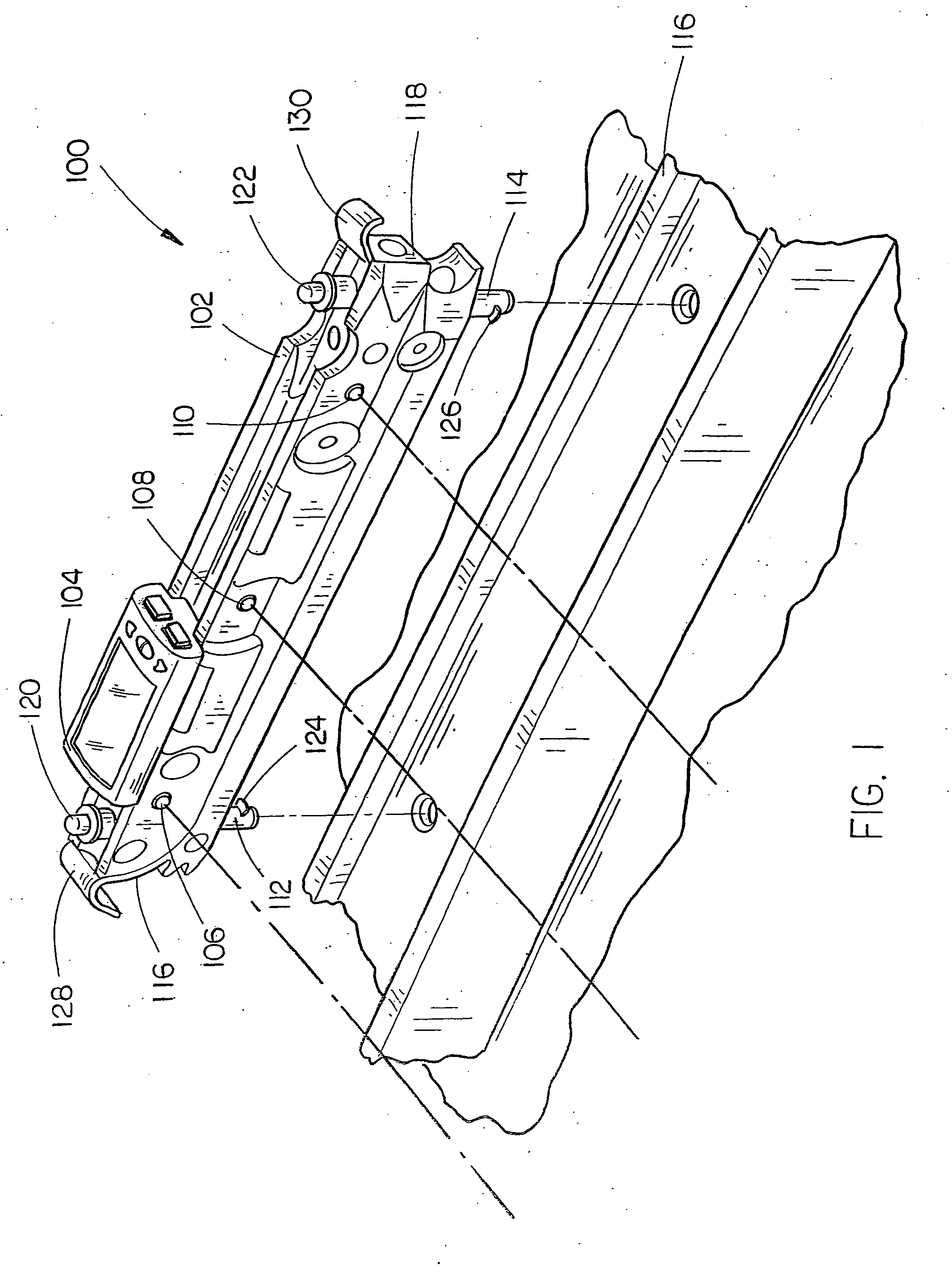
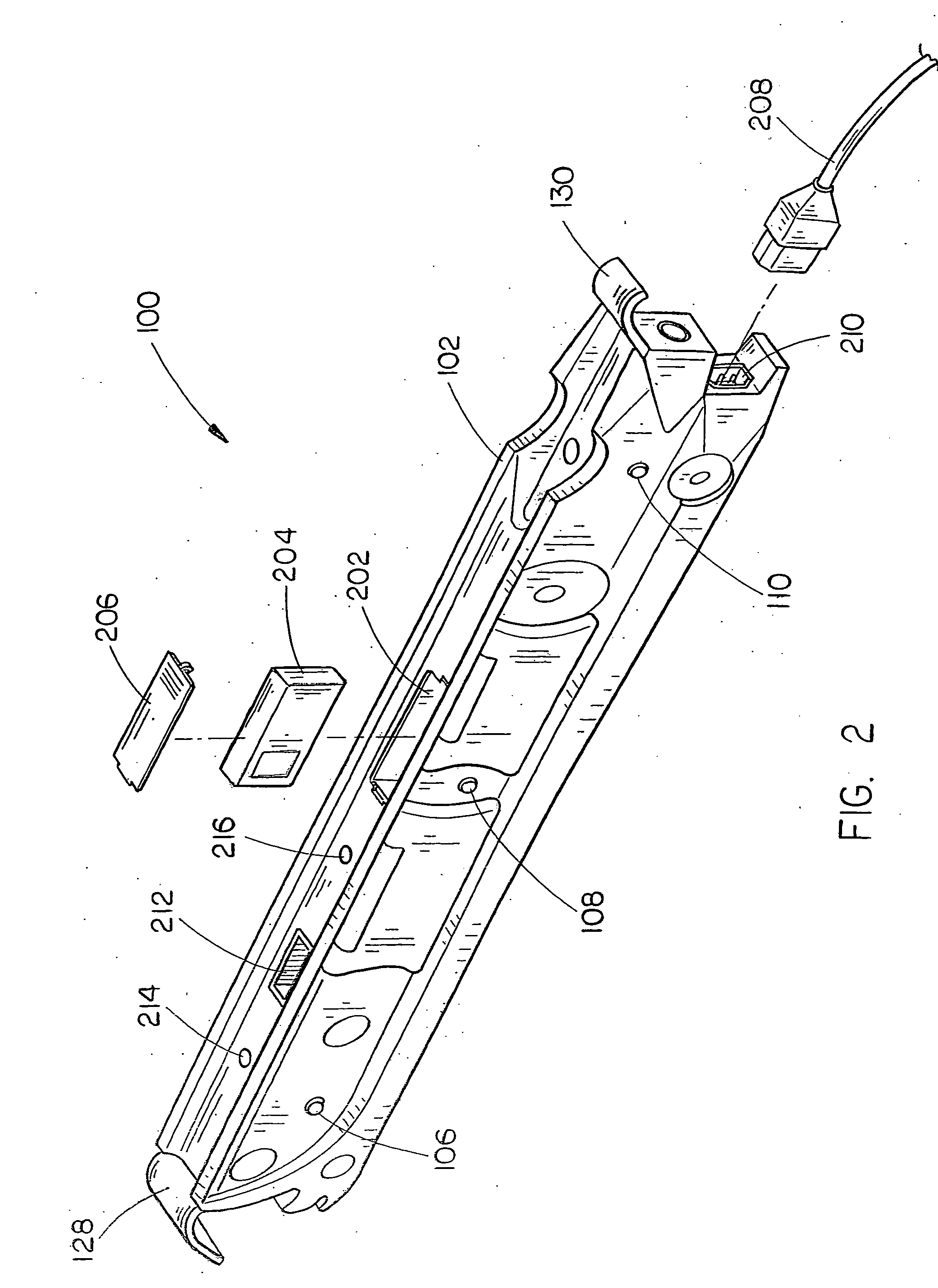
[0173] Referring generally now to FIG. 1, a laser apparatus 100 of the present invention is shown. In the present embodiment, the laser apparatus 100 comprises a housing 102 coupled with a computing system 104. Further, the housing 102 is disposed with an optical assembly including a first laser source 106, a second laser source 108, and a third laser source 110, in the preferred embodiment. Alternatively, the housing 102 may include a greater or fewer number of laser sources in order to meet the needs of a manufacturer or consumer. Each of the three laser sources 106 through 110 is in communication with the computing system 104. In the current embodiment the communicative link is a wireless system, however, a...
PUM
 Abstract
Description
Claims
Application Information