Eureka AIR delivers breakthrough ideas for toughest innovation challenges, trusted by R&D personnel around the world.

Method and device for polishing work edge

Inactive Publication Date: 2001-06-19
EMUTETABUKU
View PDF7 Cites 17 Cited by
  • Summary
  • Abstract
  • Description
  • Claims
  • Application Information

AI Technical Summary

Benefits of technology

It is another object of the invention to provide a work edge polishing device significantly inexpensive in the production cost as well as in the running cost, for example, 1 / 2 to 1 / 10 compared with the conventional device.
It is another object of the invention to yieldingly move one of the rubber wheel and the work to and from the other during polishing operation so as to moderate the polishing force eliminating the risk of strain or crack which may otherwise be caused in the work.

Problems solved by technology

Since the conventional polishing wheel is poor in the polishing ability by itself, the slurry containing diamond particles is used to polish the wafer utilizing the chemical etching effect of the slurry which is alkaline.
Such a slurry has a nature of hardening and sticking to the objects when it is retained in the tubes and the tank for a long period of time.
This will obstruct the tubes and adversely affect the electromagnetic valves.
Further the tubes must be the Teflon tubes which may be expensive 7 to 10 times as much as the ordinary vinyl tubes.
Thus the conventional polishing machine is considerably expensive in the production cost as well as in the running cost.
This will considerably reduce the operation efficiency in addition to the probability of adverse influence of the slurry etching upon the wafer.
On the other hand, if a rubber wheel containing abrasives is employed instead of the buff wheel, the rubber wheel will be rapidly abraded because the rubber wheel can not yieldingly traverse with respect to the work.
Further the rubber wheel will damage the work such as the wafer because the rubber wheel is not so soft as the buff wheel.

Method used


Image

  • Method and device for polishing work edge
  • Method and device for polishing work edge
  • Method and device for polishing work edge

Examples


Embodiment Construction

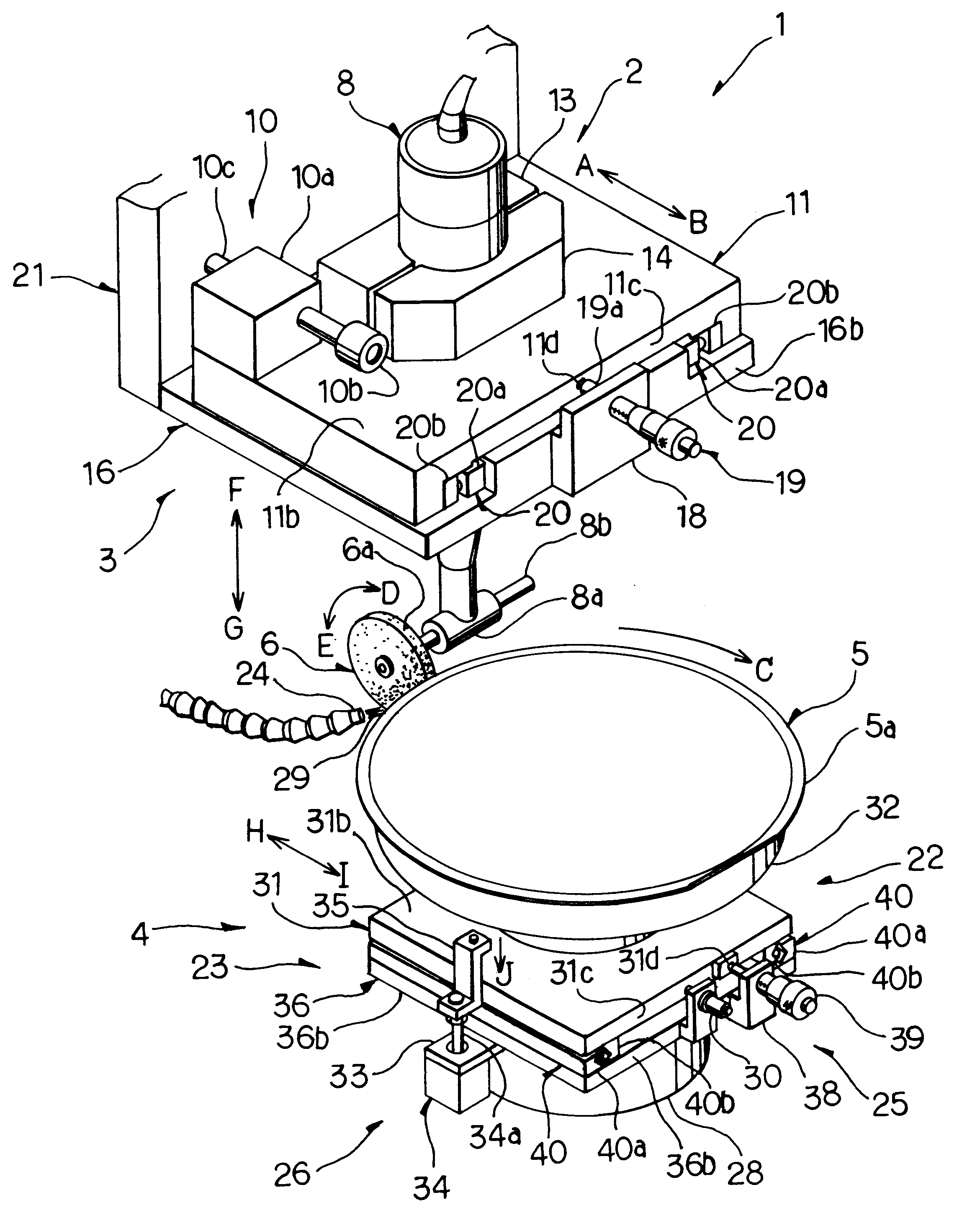
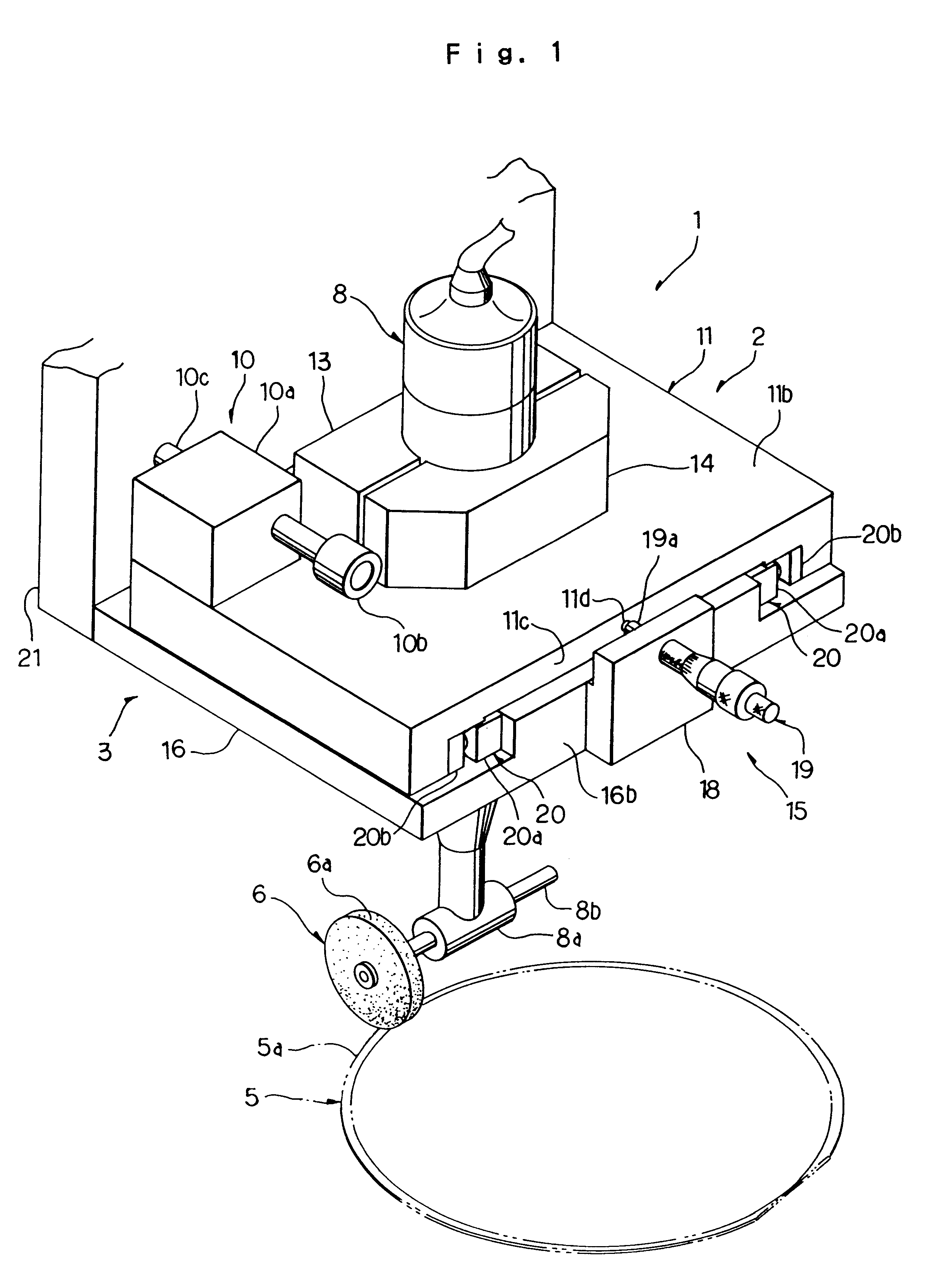
The invention will now be described in reference to the attached drawings. In FIGS. 1 and 4, the work edge polishing device 1 of the invention is substantially composed of a floating portion 2, a fixed portion 3 and a work mounting portion 4.

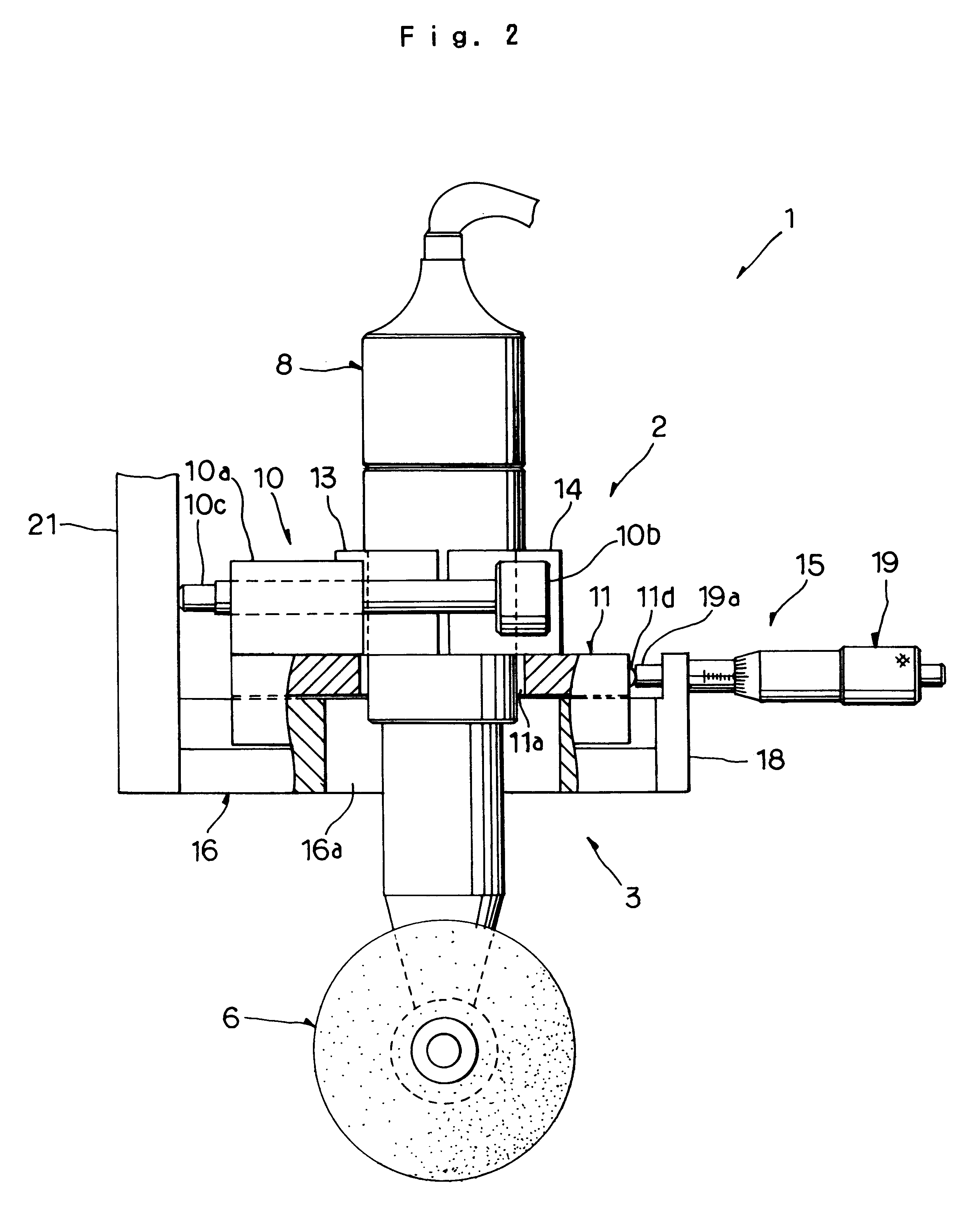
The polishing device is designed to rotate a rubber wheel 6 containing abrasives such as diamond particles to polish the edge 5a of a thin plate-like work 5 by means of the outer periphery 6a of the rubber wheel 6.

The floating portion 2 is mounted on the fixed portion 3 with a linear guide 20 being interposed therebetween and is slightly slidingly movable with respect to the fixed portion 3 in the directions in which the rubber wheel 6 and the edge 5a of the work 5 are moved toward and away from each other.

In FIGS. 1, 2 and 3, the floating portion 2 includes a floating plate 11 which is substantially of a U-shape and arranged in a horizontal plane. On the horizontal floating plate 11, there are mounted a spindle 8 for rotating the rubber wheel 6...


PUM

PropertyMeasurementUnit
Forceaaaaaaaaaa

Abstract

Method and device for polishing an edge of a work is disclosed, wherein a rubber wheel 6 containing abrasives is rotated in a plane normal to a surface of a work 5 in a form of a thin plate having an edge 5a to be polished. A spindle portion 8 holding the rubber wheel such that the rubber wheel is driven to rotate in a plane normal to the surface of the work. A mount portion 4 for mounting the work 5 thereon such that the work 5 is movable straight with respect to the rubber wheel 6 in a plane normal to the plane in which the rubber wheel 6 is rotated. Elastic means 9 is provided to urge the spindle portion 8 and the work mounting portion 4 in a direction so as to bring the rubber wheel 6 and the edge 5a of the work 5 in contact with each other, wherein one of the spindle portion 8 and the mount portion 4 is movable toward and away from the other during polishing operation.

Description

1. Field of the ArtThe invention relates to method and device for polishing the edge of a work, and more particularly relates to polishing the edge of a work by use of a rubber wheel (RBW=RUBBER BONDED WHEEL) containing abrasives, instead of using the slurry containing diamond particles for abrasives which may obstruct the tubes of the device and adversely affect the electromagnetic valves and further may be easily congealed at various places, wherein the heat produced by polishing operation is cooled down by air or water, thereby to maintain the quality of the polished work and further to significantly reduce the production cost as well as the running cost of the device.2. Prior ArtThe wafers such as silicon wafers are generally referred to the thin disk-shaped semiconductor elements, and are normally cut out from a refined cylindrical single crystal mother material. The wafer is polished on one side thereof just like a mirror surface and then the surface is provided with various s...

Claims


Application Information

Patent Timeline
IPC IPC(8): B24B41/00B24B9/06B24B9/00
CPCB24B9/065B24B41/002
Inventor OZAKI, HARUO
Owner EMUTETABUKU
Why Eureka
Eureka Blog
Learn More