Yield and line width performance for liquid polymers and other materials

a liquid polymer and line width technology, applied in the field of microelectronic fabrication, can solve the problems of not fully meeting the requirements of critical dimension control, process-induced defect count reduction, process-induced particle count reduction,

Inactive Publication Date: 2001-06-19
ASML HLDG NV
View PDF50 Cites 20 Cited by
  • Summary
  • Abstract
  • Description
  • Claims
  • Application Information

AI Technical Summary

Benefits of technology

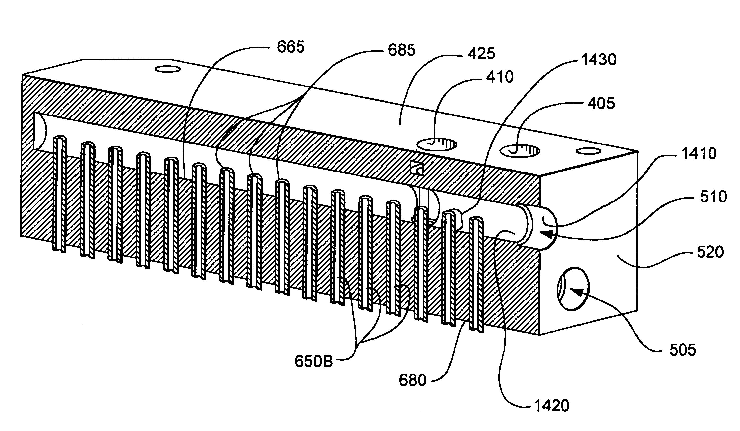
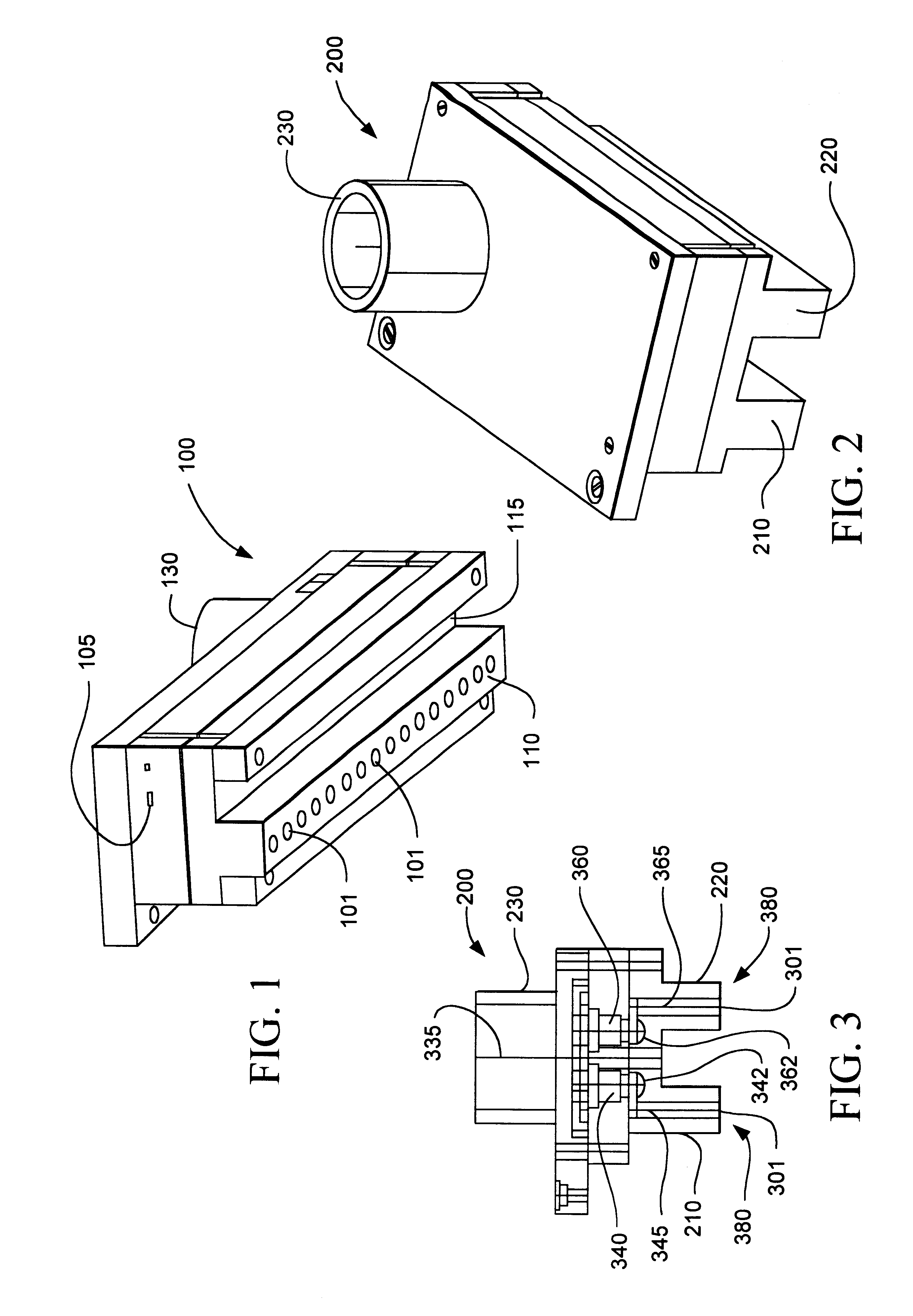
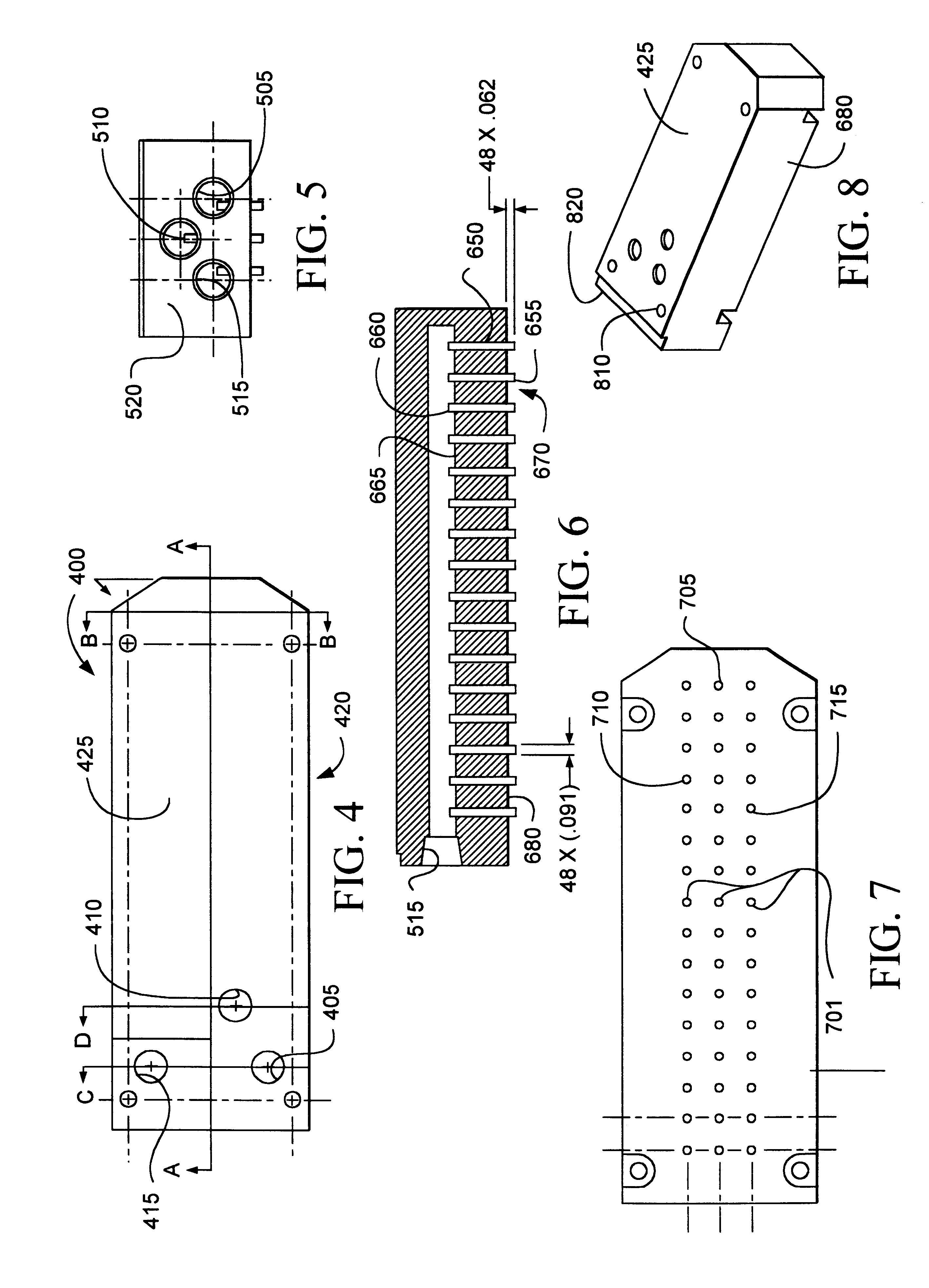
A process and / or nozzle, representing an embodiment of the invention, can be cost effective and advantageous for at least the following reasons. This invention improves the CD control capability of the developer fluid module. This invention reduces defects and particles during the develop process thereby improving the yield of the final devices. This invention combines low impingement force nozzle for both develop and rinse parts of the process and minimizes the impinging force on the features which are being developed, which in turn, minimizes the pattern collapsing, thus improving device yields. This invention has wide process latitude and reduced sensitivity to process variables. This invention includes improved rinsing action which reduces the total develop process time, thus increasing the throughput. The advantages of the nozzle include the enablement of an all-in-one design: three rows of holes for two developer chemistries and one row of holes for deionized water chemistry in a single head, if needed. The advantages of the nozzle include a compact design, for example, a nozzle width of only 1-1 / 2 inches for a triple head. The advantages of the nozzle include low cost. The advantages of the nozzle include a one piece body design that is easy to manufacture. The advantages of the nozzle include tube inserts with smooth inner surfaces for improved particle performance.All the disclosed embodiments of the invention described herein can be realized and practiced without undue experimentation. Although the best mode of carrying out the invention contemplated by the inventors is disclosed above, practice of the invention is not limited thereto. Accordingly, it will be appreciated by those skilled in the art that the invention may be practiced otherwise than as specifically described herein.For example, the individual components need not be formed in the disclosed shapes, or assembled in the disclosed configuration, but could be provided in virtually any shape, and assembled in virtually any configuration. Further, the individual components need not be fabricated from the disclosed materials, but could be fabricated from virtually any suitable materials. Further, although the multiport nozzle described herein can be a physically separate module, it will be manifest that the multiport nozzle may be integrated into the apparatus with which it is associated. Furthermore, all the disclosed elements and features of each disclosed embodiment can be combined with, or substituted for, the disclosed elements and features of every other disclosed embodiment except where such elements or features are mutually exclusive.It will be manifest that various additions, modifications and rearrangements of the features of the invention may be made without deviating from the spirit and scope of the underlying inventive concept. It is intended that the scope of the invention as defined by the appended claims and their equivalents cover all such additions, modifications, and rearrangements. The appended claims are not to be interpreted as including means-plus-function limitations, unless such a limitation is explicitly recited in a given claim using the phrase "means-for." Expedient embodiments of the invention are differentiated by the appended subclaims.

Problems solved by technology

Heretofore, the requirements of improved critical dimension control, reduced process-induced defect counts and reduced process-induced particle counts referred to above have not been fully met.

Method used


Image

  • Yield and line width performance for liquid polymers and other materials
  • Yield and line width performance for liquid polymers and other materials
  • Yield and line width performance for liquid polymers and other materials

Examples


Embodiment Construction

The invention and the various features and advantageous details thereof are explained more fully with reference to the nonlimiting embodiments that are illustrated in the accompanying drawings and detailed in the following description of preferred embodiments. Descriptions of well known components and processing techniques are omitted so as not to unnecessarily obscure the invention in detail.

The context of the invention includes photolithography processing of micro structures (e.g., microelectronic structures). These structures are typically etched and the polymers of interest function as masks to shield portions of the structures that are to remain at least largely unaffected by the etchant. The polymers that are being developed can be negative and / or positive photoresists. The invention can also utilize data processing methods that transform signals that characterize the state of the polymer processing so as to actuate interconnected discrete hardware elements; for example, to re...


PUM

PropertyMeasurementUnit
distanceaaaaaaaaaa
distanceaaaaaaaaaa
distanceaaaaaaaaaa

Abstract

Systems and methods are described for improved yield and line width performance for liquid polymers and other materials. A method for minimizing precipitation of developing reactant by lowering a sudden change in pH includes: developing at least a portion of a polymer layer on a substrate with an initial charge of a developer fluid; then rinsing the polymer with an additional charge of the developer fluid so as to controllably minimize a subsequent sudden change in pH; and then rinsing the polymer with a charge of another fluid. An apparatus for minimizing fluid impingement force on a polymer layer to be developed on a substrate includes: a nozzle including: a developer manifold adapted to supply a developer fluid; a plurality of developer fluid conduits coupled to the developer manifold; a rinse manifold adapted to supply a rinse fluid; and a plurality of rinse fluid conduits coupled to the developer manifold. The developer manifold and the rinse manifold can be staggered so as to reduce an external width of the nozzle compared to a nominal external width of the nozzle achievable without either intersecting the fluid manifold and the another manifold or staggering the fluid manifold and the another manifold. The systems and methods provide advantages including improve yield via reduced process-induced defect and partial counts, and improved critical dimension (CD) control capability.

Description

1. Field of the InventionThe invention relates generally to the field of microelectronic fabrication. More particularly, the invention relates to improving the yield and line width performance of liquid polymers.2. Discussion of the Related ArtLithography process is one of the major drivers of semiconductor industry in its relentless progress in achieving smaller feature sizes with improved yields. More specifically, improved critical dimension (CD) control and reduced process-induced defect and particle counts need to be satisfied simultaneously.The develop fluid module process plays a significant role in the patterning of increasingly smaller line widths. Regions of high and low dissolution rates are created on the resist film as a result of the sequence of photolithography process steps preceding the develop process. During a develop process, images transferred to the resists film are developed into three dimensional structures by a wet process. The subsequent etch process (mostl...

Claims


Application Information

Patent Timeline
Patent Type & Authority Patents(United States)
IPC IPC(8): B05C5/02B05C11/08G03F7/30B05B7/08B05B7/02H01L21/027
CPCB05C5/027B05C11/08G03F7/3021G03F7/322H01L21/67051B05B7/0884
Inventor GURER, EMIRLEE, ED C.KRISHNA, MURTHYREYNOLDS, REESESALOIS, JOHNCHERRY, ROYAL
Owner ASML HLDG NV
Why Eureka
Try Eureka