Accumulating automatic skimmer

a technology of automatic skimmer and accumulator, which is applied in the direction of filtration separation, water cleaning, separation process, etc., can solve problems such as errors reported, and achieve the effect of reliable operation

Inactive Publication Date: 2001-06-26
DOUGLAS ENG DIV U S HYDREX
View PDF10 Cites 36 Cited by
  • Summary
  • Abstract
  • Description
  • Claims
  • Application Information

AI Technical Summary

Benefits of technology

The nature of the floating weir is to create a void space behind the weir which has a tendency to cause the body of the skimmer to rise out of the water. As the skimmer rises, the floats are elevated and displacement is lost; ultimately, an equilibrium is established between the rise of the skimmer and the loss of displacement. This change in elevation in relation to the external water level is measured by instrumentation (float switch or ultrasonic level indicator for instance) and logged into the logic controls, thus allowing an accurate reporting of the skim status of the skimmer. If the external water level fails to reach the prescribed level, the logic unit can take corrective steps. In this preferred embodiment, the logic unit will shut down any pumps which are on and allow the system to remain dormant for a period of time; it will then resume the pumping. This procedure may be repeated several times before the skimmer pumps are shut down and an error condition is reported. The assumption behind this type of action is that any correctable problem is due to debris somehow lodging into the moving parts of the skimmer and cessation and resumption of skimming can often clear these problems. It has been observed that particularly viscous oils can prevent liquid from entering the skimmer, but cessation and resumption can overcome this problem.
Because the present invention allows for the accurate presentation of the status of the skimmer and the liquid inside it, the logic controls can direct the operation of the skimmer to suit the needs of the situation. In one embodiment, the logic controls monitor a fluid level switch which measures the level of the liquid in an oil recovery tank which accepts the oil output of the skimmer. The logic controls can therefore suspend oil recovery and signal a "recovery tank full" condition. The logic controls may also determine if oil recovery has occurred over a period of time (example, eight hours of skimming) and if no such oil recovery has occurred, the skimmer can be shut down until the next "start cycle" event occurs.
It is thus an object of the invention to provide automatic operation in separation of two different-density liquids, preferably petroleum derivative and water, with reliable operation, in a situation where human observation and operation are inconvenient or difficult.
FIG. 13 is a simple flow chart indicating automatic operation of the system of the invention.

Problems solved by technology

This procedure may be repeated several times before the skimmer pumps are shut down and an error condition is reported.
The assumption behind this type of action is that any correctable problem is due to debris somehow lodging into the moving parts of the skimmer and cessation and resumption of skimming can often clear these problems.

Method used


Image

  • Accumulating automatic skimmer
  • Accumulating automatic skimmer
  • Accumulating automatic skimmer

Examples


Embodiment Construction

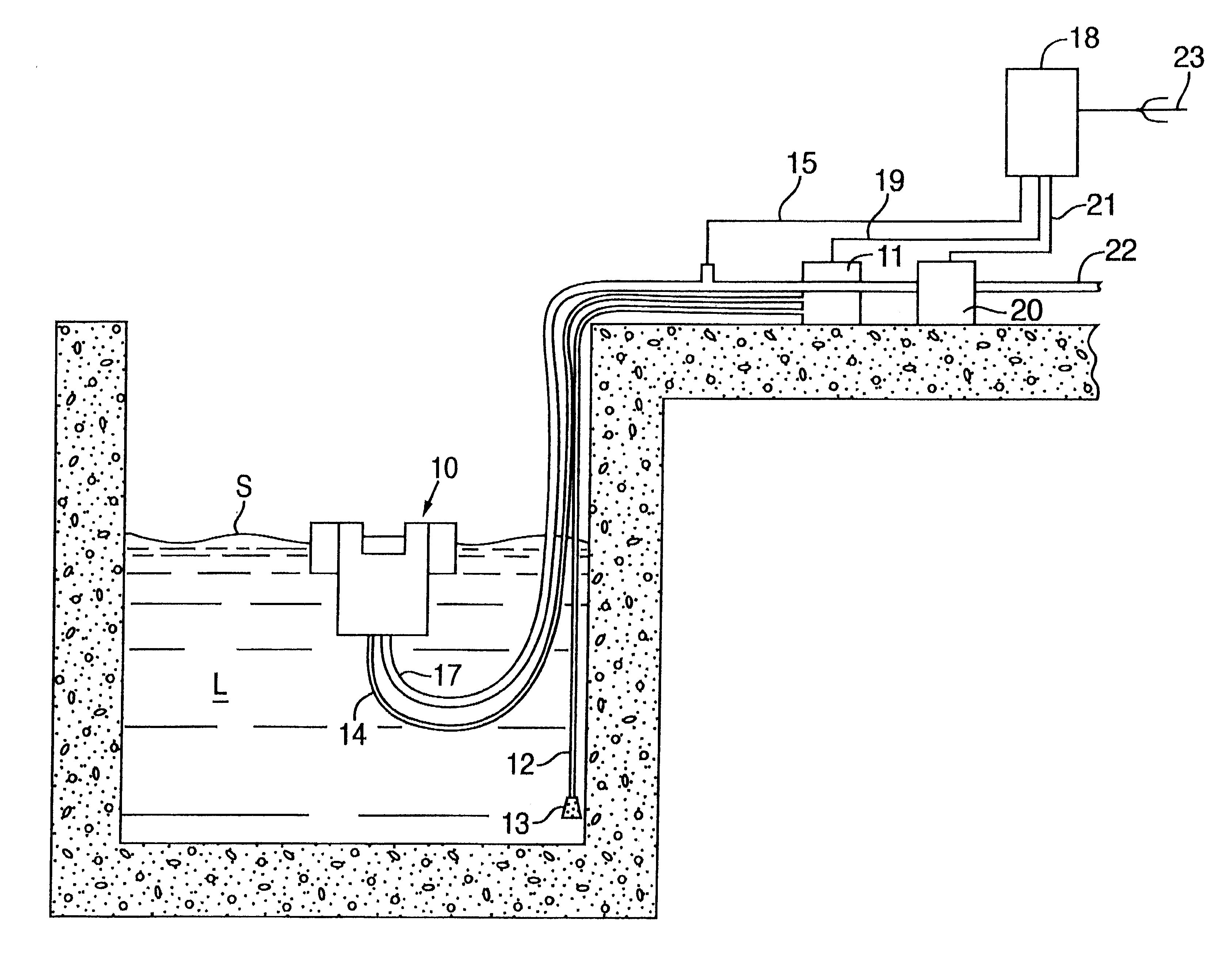
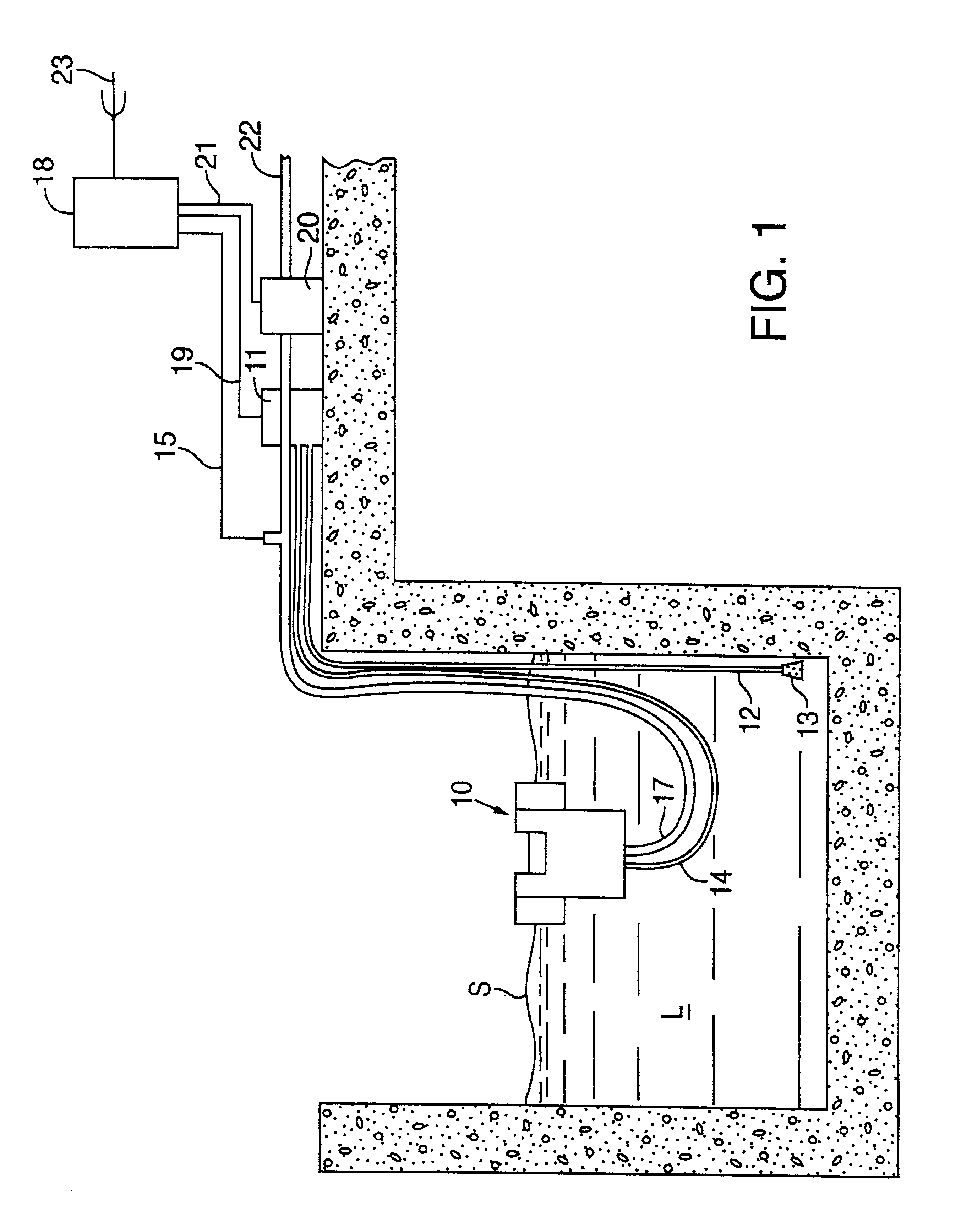
As best illustrated in FIG. 1, a floating skimmer 10 is constructed to skim the surface S of a liquid L, accumulating the skimmed material for removal. In one of several possible arrangements, a water pump 11 takes input via a conduit 12 which may have a screen 13 attached to prohibit debris from entering the conduit and thus interfering with the pump 11. The output of pump 11 is directed via a conduit 14 to a venturi type pump (as described below) in the body of skimmer 10. This establishes the skim of the surface S of the liquid L. Electrical signals or the equivalent such as light or air pressure are transferred from skimmer instrumentation (as described below) via a conduit 15 which runs through an oil hose 17 to control circuitry 18. In consideration of explosive environments associated with volatile vapors from surface S, all signals in the conduit 15 should be intrinsically safe as defined by the National Electric Code.

The control circuitry 18 controls the water pump 11 via a...


PUM

PropertyMeasurementUnit
timeaaaaaaaaaa
specific gravityaaaaaaaaaa

Abstract

A floating skimmer is used for automatically removing oil and other floating matter from the surface of liquid surrounding the skimmer, preferably in a basin or sump. Floats around the periphery and above the general body of the skimmer provide flotation while the unit is at rest. Two liquid removal devices are provided, one to remove the most dense liquid (generally oil) accumulated in the skimmer sump. A gasketed, hinged, floating weir rests on the fluid level in the skimmer sump and when liquid is removed from the sump by either the first or second device or a combination of both, the weir falls back, creating a cascade action which attracts the surface of surrounding liquid into the skimmer sump. Instrumentation is included to provide information for automatic operation and status reporting of the skimmer.

Description

This invention relates to a method and apparatus for cleaning the surface of liquid in a reliable and automated manner.Many industrial, military and municipal facilities have separation tanks, sumps, lift stations and the like which must have oil or other floating material removed from the surface of the water in these facilities. In general, these tanks and sumps are not hospitable to human observation and consequently, they are not easily cleaned by standard methods. This invention provides a means for accurate reporting of the skimmer related conditions in such tanks and sumps, the control of debris, and the removal of oil accumulations.Skimmers described in the prior art either deliver an oil and water output which must be separated by an expensive process or require the movement of physical means into the liquid layer to adsorb the oil, a process which is difficult to maintain and often provides unreliable performance. This invention attracts and collects floating oil and debri...

Claims


Application Information

Patent Timeline
Patent Type & Authority Patents(United States)
IPC IPC(8): B01D17/02E03F5/14E03F5/16C02F1/40
CPCB01D17/0214E03F5/16C02F1/40Y10S210/923
Inventor GORE, DOUGLAS J.
Owner DOUGLAS ENG DIV U S HYDREX
Why Eureka
Try Eureka